Five-axis CNC with Marlin2ForPipetBot
Marlin for five-axis CNC
Marlin2ForPipetBot is a fork of Marlin firmware that adds support for true simultaneous 5 axis machining with rotational tool centerpoint control (TCPC) for multi axis CNC machines. It adds the G-code G43.4 which is a command to control the tool centerpoint (TCP) relative to the part during multi axis machining.
Video 1: Demonstration of tool centerpoint control (TCPC) on the machine XYZBC_TRT_SKR-A8 by DerAndere. Copyright 2024 DerAndere. This video is licensed under the Creative Commons Attribution 4.0 International License. To view a copy of this license, visit http://creativecommons.org/licenses/by/4.0/. The .mp4 file can be downloaded here.
To set up Marlin2ForPipetBot for a 5 axis CNC machine, follow these instructions.
PENTA_AXIS_TRT
One of the most common five-axis CNC machine geometries features a tilting rotating table. Several settings must be configured correctly to make G43.4 (TCPC) work, as described below. To set the correct kinematics for this machine geometry, enable this option in Configuration.h:
#define PENTA_AXIS_TRT
DEFAULT_MRZP_OFFSET_X, DEFAULT_MRZP_OFFSET_Y, DEFAULT_MRZP_OFFSET_Z:
For machines with a tilting rotating table (XYZAC or XYZBC) the machine rotary zero point (MRZP) offset is the position of the center of rotation (P) in machine coordinates. The center of rotation is usually the center of the top surface of the rotary table when all axes are at position 0 (in machine coordinates). In other words, the offsets are equal to the distance along the respective axis (X, Y, Z) from the origin O(0,0,0) to the intersection P between the top surface of the rotary table and the verical centerline of joint 5.
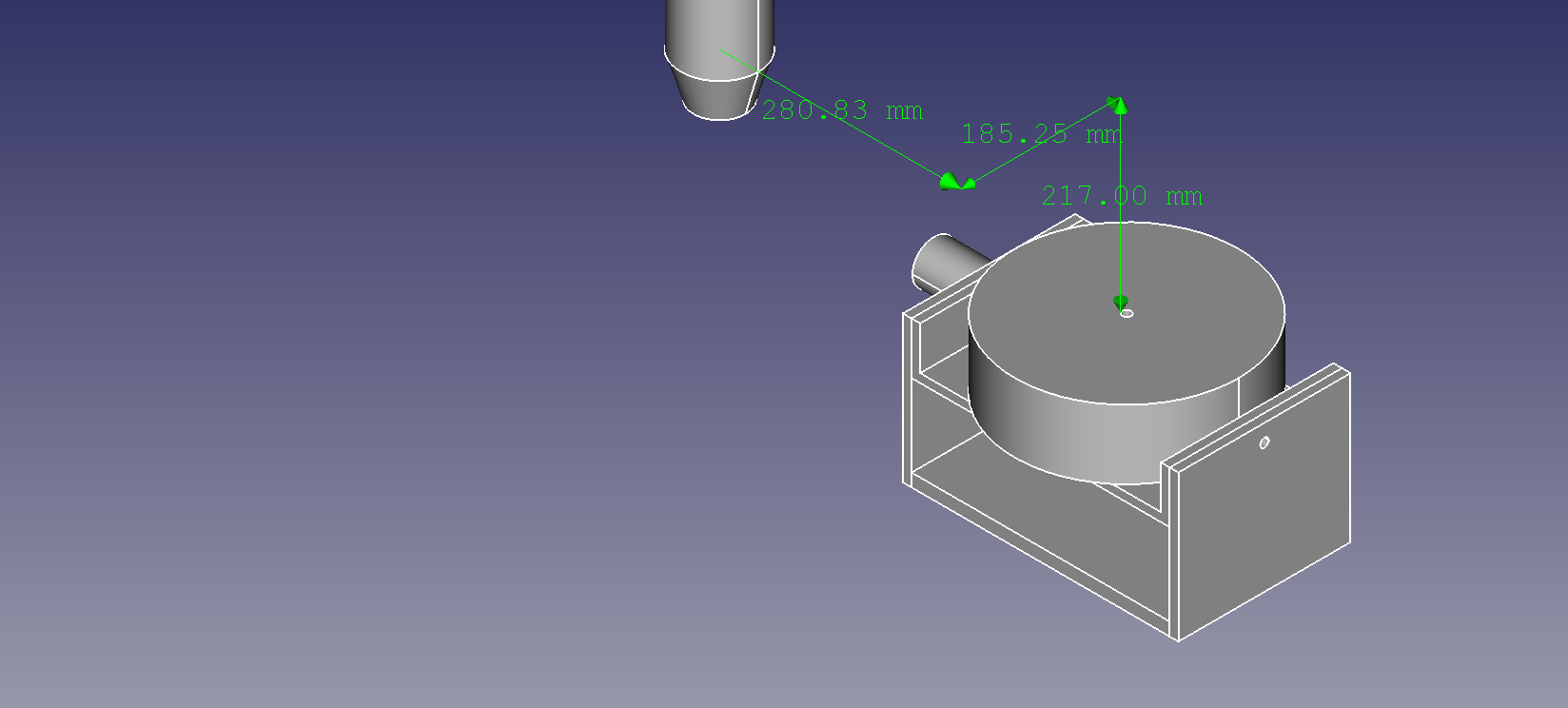 Figure 1: MRZP offsets of a CNC machine with five axes (XYZAC), featuring a tilting rotating table. Note that the image shows the machine in a state where all axes are in neutral position (position 0 in machine coordinates) so that the tilting rotating table is oriented horizontally. Copyright 2024 DerAndere. This image is licensed under the terms of the GNU General Public License, version 3.0 or later, or it is licensed under the terms of the Creative Commons Attribution 4.0 International license (CC BY 4.0).
The machine in figure 1 would thus have the following settings defined in Configuration.h:
#define DEFAULT_MRZP_OFFSET_X  280.83
#define DEFAULT_MRZP_OFFSET_Y  185.25
#define DEFAULT_MRZP_OFFSET_Z -217.00
DEFAULT_ROTATIONAL_JOINT_OFFSET_X, DEFAULT_ROTATIONAL_JOINT_OFFSET_Y, DEFAULT_ROTATIONAL_JOINT_OFFSET_Z
For machines with a tilting rotating table, the rotational joint offset is the distance between the centers of rotation of joints 4 and 5.
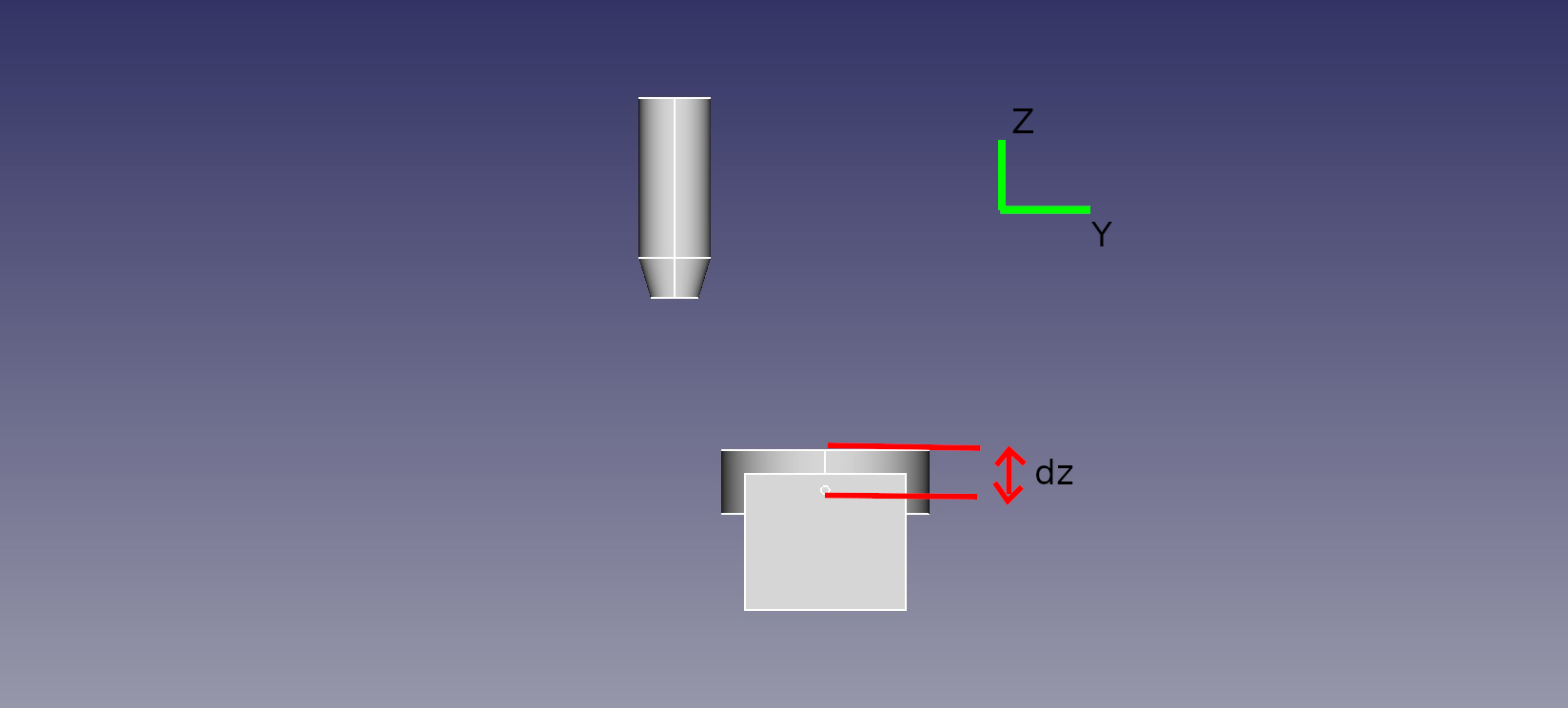 Figure 2: Negative rotational joint Z offset of a CNC machine with five axes (XYZAC) with a tilting rotating table. Note that the image shows the machine in a state where all axes are at position 0 (in machine coordinates) so that the tilting rotating table is oriented horizontally. The rotational joint Z offset is represented as distance dz. This image is licensed under the terms of the GNU General Public License, version 3.0 or later, or it is licensed under the terms of the Creative Commons Attribution 4.0 International license (CC BY 4.0).
For the machine depicted in figure 2 with a rotational joint Z offset of dz = -50 mm, rotational joint offsets would be set as follows in Configuration.h:
#define DEFAULT_ROTATIONAL_JOINT_OFFSET_X  0.00
#define DEFAULT_ROTATIONAL_JOINT_OFFSET_Y  0.00
#define DEFAULT_ROTATIONAL_JOINT_OFFSET_Z -50.00
An asymmetic tilting rotating table has rotational joint offsets along two axes as shown in figure 3.
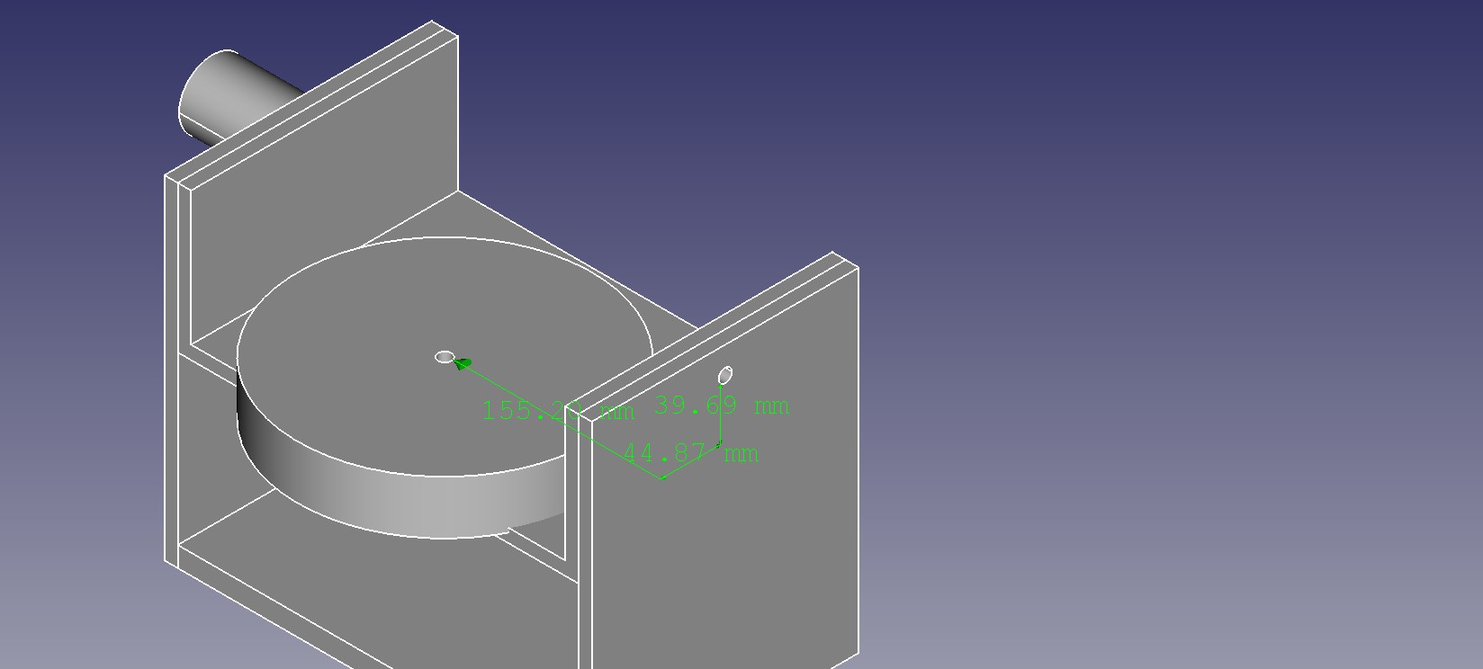 Figure 3: Rotational joint offsets of a CNC machine with five axes (XYZAC) with an asymmetric tilting rotating table. Note that the image shows the machine in a state where all axes are in neutral position (position 0 in machine coordinates) so that the tilting rotating table is oriented horizontally. The rotational joint y offset of this machine is dy = 44.87 and the rotational joint z offset is dz = 39.69. This image is licensed under the terms of the GNU General Public License, version 3.0 or later, or it is licensed under the terms of the Creative Commons Attribution 4.0 International license (CC BY 4.0).
For the machine depicted in figure 3 with a rotational joint Y offset of dy = 44.87 and a rotational joint Z offset of dz = 39,69 mm, the follows settings are required in Configuration.h:
#define DEFAULT_ROTATIONAL_JOINT_OFFSET_X   0.00
#define DEFAULT_ROTATIONAL_JOINT_OFFSET_Y  44.87
#define DEFAULT_ROTATIONAL_JOINT_OFFSET_Z 39,69
Appendix 1
The following source code can be used to check the inverse kinematics function:
/**
 * penta_axis_trt_test
 * Copyright 2022 DerAndere
 * SPDX-License-Identifier: GPL-3.0
 *
 * Based on the file trtfuncs.c from LinuxCNC (https://github.com/LinuxCNC/linuxcnc/blob/master/src/emc/kinematics/trtfuncs.c)
 * Copyright 2016 Rudy du Preez <rudy@asmsa.co.za>
 * Author: Rudy du Preez <rudy@asmsa.co.za>
 */

/**
 * @file penta_axis_trt_test.cpp
 * @author DerAndere
 * @brief Kinematics for a 5 axis CNC machine in tilting rotating table configuration.
 *
 *  A) XYZAC_TRT:
 *     This machine has a tilting table (A axis paralel to the X axis) and horizontal rotary
 *     mounted to the table (C axis).
 *  B) XYZBC_TRT:
 *     This machine has a tilting table (B axis paralel to the Y axis) and horizontal rotary
 *     mounted to the table (C axis).
 *
 * Copyright 2022 DerAndere
 *
 * Based on the file trtfuncs.c from LinuxCNC (https://github.com/LinuxCNC/linuxcnc/blob/master/src/emc/kinematics/trtfuncs.c)
 * Copyright 2016 Rudy du Preez <rudy@asmsa.co.za>
 * Author: Rudy du Preez <rudy@asmsa.co.za>
 */

#include <iostream>
#include <vector>
#include <cmath>

#define NUM_AXIS 5
#define AXIS4_NAME 'B'
#define RADIANS(d) ((d)*float(M_PI)/180.0f)

float mrzp_offset_x = 0.0f;
float mrzp_offset_y = 0.0f;
float mrzp_offset_z = 0.0f;

float x_offset = 0.0f;
float y_offset = 0.0f;
float z_offset = 0.0f;

float hotend_offset_x = -10.0f;
float hotend_offset_y = -10.0f;
float hotend_offset_z = -10.0f;

std::vector<float> native_to_joint(const std::vector<float> native) {

  const float pivot_length_x = native[0] - mrzp_offset_x;
  const float pivot_length_y = native[1] - mrzp_offset_y;
  const float pivot_length_z = native[2] - mrzp_offset_z;

  const float i_rad = RADIANS(native[3]);
  const float j_rad = RADIANS(native[4]);

  const float cos_i = cos(i_rad);
  const float sin_i = sin(i_rad);
  const float cos_j = cos(j_rad);
  const float sin_j = sin(j_rad);

  #if AXIS4_NAME == 'A'
    // computed position
    const std::vector<float> joints_pos = {
        cos_j      * pivot_length_x
      - sin_j      * pivot_length_y
      + mrzp_offset_x - hotend_offset_x,

        sin_j * cos_i * pivot_length_x
      + cos_j * cos_i * pivot_length_y
      -         sin_i * pivot_length_z
      -         cos_i * y_offset
      +         sin_i * z_offset
      + y_offset
      + mrzp_offset_y - hotend_offet_y,

        sin_j * sin_i * pivot_length_x
      + cos_j * sin_i * pivot_length_y
      +         cos_i * pivot_length_z
      -         sin_i * y_offset
      -         cos_i * z_offset
      + z_offset
      + mrzp_offset_z - hotend_offset_z,

        native[3],

        native[4]
    };
  #elif AXIS4_NAME == 'B'
    // computed position
    const std::vector<float> joints_pos = {
        cos_j * cos_i * pivot_length_x
      - sin_j * cos_i * pivot_length_y
      -         sin_i * pivot_length_z
      -         cos_i * x_offset
      +         sin_i * z_offset
      + x_offset
      + mrzp_offset_x - hotend_offset_x,

        sin_j      * pivot_length_x
      + cos_j      * pivot_length_y
      + mrzp_offset_y - hotend_offset_y,

      + cos_j * sin_i * pivot_length_x
      - sin_j * sin_i * pivot_length_y
      +         cos_i * pivot_length_z
      +         sin_i * x_offset
      -         cos_i * z_offset
      + z_offset
      + mrzp_offset_z - hotend_offset_z,

        native[3],

        native[4]
    };
  #endif


  return joints_pos;
}

int main() {
  std::vector<float> test_nat_pos = {0.0f, 5.0f, 0.0f, 90.0f, 90.0f};

  std::vector<float> test_joints_pos = native_to_joint(test_nat_pos);

  std::cout<<"native:"<<"\n";
  for (int i=0; i<NUM_AXIS; ++i) {
    std::cout<<test_nat_pos[i]<<"\n";
  }

  std::cout<<"joints:"<<"\n";
  for (int i=0; i<NUM_AXIS; ++i) {
    std::cout<<test_joints_pos[i]<<"\n";
  }
  return 0;
}
Copyright 2024 DerAndere