DIY lab robot Pipetbot-A8
Overview
Pipetbot-A8 is a proof of principle lab liquid handler for under €200.
Core components: Anet A8 frame and board, syringe pump module, Marlin2ForPipetBot firmware, GGCGen for G-code generation, pyotronext backend.
Video 1: Introdution to the PipetBot and the robot control software GGCGen. Copyright 2019 DerAndere. This video is licensed under the terms of the Creative Commons Attribution 4.0 International license (CC BY 4.0).
Video 2: Demonstration of the liquid handling robot PipetBot-A8 in action. Copyright 2019 DerAndere. This video is licensed under the terms of the Creative Commons Attribution 4.0 International license (CC BY 4.0).
Alternatives that have been considered
[Werbung ohne Auftrag / unpaid advertisement]
Traditionally, an Arduino Mega compatible development board equipped with a CNC shield or a RepRap Arduino Mega Pololu Shield (RAMPS 1.4) is a common starting point for the development of CNC machines. Examples are the SCARA robot by Oscar Gonzalez, the Biobot by a team at the University of Serbrooke with its nice 3D models or the Evobot that was developed as part of the EVOBLISS project at IT University of Copenhagen.The RAMPS 1.4 is open source hardware and offers more flexibility than the Anet-V1.0 controller board that is included in the Anet A8 The blogger “Pipette Jockey” built his “Aliqbot” using an MKS sbase 1.3. He even made his pipetting robot compatible with the Opentrons open source software framework without using a raspberry pi (running all the Opentrons software on a regular computer). I invite you to visit his website www.pipettejockey.com to follow his advances in building open lab equipment and establishing protocols for the biochemistry lab that are open to the public.
Since stepper motors are prone to loosing steps and because closed loop control is required for reliable positioning, they could be replaced by servo motors (DC motor + position encoder). The UHU Servo Controller 3.00 (15 € + shipment from Germany) or the Tarocco driver board (65 $, open source, see the repository on https://github.com for details) allow closed-loop control of brushed DC motors in combination with position encoders using the same step/dir wiring interface that is traditionally used to control stepper motors. Brushed DC motors with optical position encoders can be easily scraped from old inkjet printers. However, I focused on the software development and used the most economic hardware setup I could come up with for testing. The Anet A8 by Shenzen Anet Technology Inc. is a Prusa i3 knock-off.
Hardware setup and firmware installation
I modified Marlin firmware to add multi-axis support. The result is Marlin2ForPipetBot firmware for CNC machines (3D printers, mills, laser cutters, hot wire foam cutters, lab robots). This firmware supports additional axes (stepper motors). Some of my changes were merged into official Marlin firmware. You can read about the development process in a separate blog post.
In order to convert the Anet A8 into a lab robot, I modified the open source firmware Marlin 2.0. The Skynet3D project had added support for the Anet A8 to official Marlin firmware. Since the merge, the Skynet3D fork is now obsolete. Marlin 2.0.x also supports a wide range of other controller boards, including boards with 32bit microcontrollers like the NXP LPC1768, the Microchip Atmel SAM3X8E (both based on an ARM Cortex M3 core). Instructions on how to install Marlin 2.0.x on different controller boards are available.
In case you need the original Anet A8 firmware:
Source code: https://anet3d.com/blogs/download/open-source-firmware-of-a8. It is based on Repetier firmware. Compiled stock firmware: https://www.bastelbunker.de/mein-3d-drucker-der-anet-a8/ It can be flashed (uploaded to the microcontroller of the control board) using the included AVRdudess.
As described at https://shop.anet3d.com/blogs/a-series/how-to-connect-anet-a8-3d-printer-to-a-pc-via-usb, updated drivers for the 3D-printer USB serial port chip CH340G/Ch341 can be downloaded from the homepage of the chip’s manufacturer Winchiphead / Nanjing QinHeng Electronics Co., Ltd: http://www.wch-ic.com/downloads/CH341SER_EXE.html.
The specific steps to install the firmware on the Anet V1.0 board of the Anet A8 are:
-
Make sure the driver for the CH341 USB Serial communication chip is properly installed and the computer is restarted before the Anet A8 is connected to the USB port of the personal computer.
-
Make sure that no software is installed that blocks the USB serial ports (COM-ports under Microsoft Windows). For example, the Repetier Server has to be uninstalled.
-
Install the Arduino IDE version 1.8.7 or newer.
-
Download the SkyNet3D board definition for the Anet V1.0 board and extract it. Combine the folder “hardware” from the zip archive with the folder “hardware” in the program directory of the Arduino IDE.
-
Start the Arduino IDE and go to Sketch > Include Library > Manage Libraries and search for the library u8glib and install it (only needed if you do not use Marlin2forPipetBot but original Marlin and want to use an LCD display). Instead of installing the original u8glib, you might need to download U8glib-HAL and extract the content from the downloaded zip-archive into the directory where the Arduino IDE is looking for libraries.
-
It is recommended to burn the Optiboot bootloader using an Arduino-compatible development board as an Inter System Programmer (ISP). A Tutorial on how to burn the bootloader on the Anet V1.0 board is available. For this step, all additional peripherals have to be disconnected from the Anet V1.0 board and the board has to be powered via the 3D printer’s power supply. For the burning of the bootloader, only the Arduino-compatible board used as an ISP must be connected to the USB port of the personal computer.
-
For flashing Marlin on the controller board using PlatformIO, instructions are available. For the Anet-V1.0 board with optiboot boatloader, change file platformio.ini , section
[PlatformIO], to specify the correct default environment, which isdefault_envs: melzi_optiboot(For the Anet-V1.0 board with standard Arduino bootloader, choose
default_envs: melzi).
My Marlin2ForPipetBot firmware is a modified version of Marlin 2.0, Free pins can be used as GPIO pins and can be set up as analog input pins for sensor input, as digital I/O pins, or as servo-pins. Briefly, retrieve the files from the branch Marlin2ForPipetBot, left-click on “clone or download” and either download the software as a .zip archive and extract it or clone that branch of the git repository (e.g. using “Visual Studio Code” with the plug-in “PlatformIO”). Alternatively, download the latest Marlin2ForPipetBot-2.0.x tagged release. If you have a controller board other than the Anet V1.0, edit the files platformio.ini, Configuration.h and Configuration_adv.h in the main folder /Marlin/ , as well as the pin file for your board (pins_YOURMOTHERBOARD.h) to match your needs. Example configs for Marlin 2.0.x do not work out of the box but can be used as a reference.
The difference between the Marlin2ForPipetBot configuration and the example configuration in
https://github.com/MarlinFirmware/Configurations/tree/bugfix-2.1.x/config/examples/Anet/A8 is that the in the former required pins for the stepper motor that drives
the syringe pump are defined. I repurposed the extruder stepper as an additional rotational axis (AXIS4_NAME 'U').
To make this possible, in the Configuration.h file, I applied the following changes:
| old setting | new setting | notes |
|---|---|---|
//#define I_DRIVER_TYPE A4988 |
//#define I_DRIVER_TYPE A4988 |
[1] |
#define AXIS4_NAME 'A' |
#define AXIS4_NAME 'U' |
[2] |
#define AXIS4_ROTATES |
//#define AXIS4_ROTATES |
[3] |
#define EXTRUDERS 1 |
#define EXTRUDERS 0 |
[4] |
//#define USE_I_MIN_PLUG |
#define USE_I_MIN_PLUG |
[5] |
//#define I_ENABLE_ON |
#define I_ENABLE_ON |
|
//#define I_MIN_POS 0 |
#define I_MIN_POS 0 |
|
//#define I_MAX_POS 10 |
#define I_MAX_POS 10 |
[6] |
//#define I_HOME_DIR -1 |
#define I_HOME_DIR -1 |
|
//#define DEFAULT_IJERK 3 |
#define DEFAULT_IJERK 3 |
[7] |
//#define I_MAX_POS 10 |
#define I_MAX_POS 10 |
[8] |
#define DEFAULT_AXIS_STEPS_PER_UNIT {} |
#define DEFAULT_AXIS_STEPS_PER_UNIT {} |
[9\ |
#define DEFAULT_MAX_FEEDRATE {} |
#define DEFAULT_MAX_FEEDRATE {} |
[9\ |
#define DEFAULT_MAX_ACCELERATION {} |
#define DEFAULT_MAX_ACCELERATION {} |
[9\ |
In Configuration_adv.h, apply the following changes:
| old setting | new setting | notes |
|---|---|---|
#define HOMING_FEEDRATE_MM_M {} |
#define HOMING_FEEDRATE_MM_M {} |
|
#define AXIS_RELATIVE_MODES {} |
#define AXIS_RELATIVE_MODES {} |
|
#define MICROSTEP_MODES {} |
#define MICROSTEP_MODES {} |
|
#define HOMING_BUMP_DIVISOR {} |
#define HOMING_BUMP_DIVISOR {} |
[9] |
#define HOMING_BACKOFF_POST_MM {} |
#define HOMING_BACKOFF_POST_MM {} |
[9] |
#define BACKLASH_DISTANCE_MM {} |
#define BACKLASH_DISTANCE_MM {} |
[9] |
In the file pins_ANET_10.h I changed pins for the extruder stepper to assign a dummy pin number (e.g. 10, but any unused pin number will do). if you use a different motherboard, change the respective pins_YOURMOTHERBOARD.h file, instead:
| old setting | new setting | notes |
|---|---|---|
#define E_STEP_PIN 1 |
#define E_STEP_PIN 10 |
[12] |
#define E_ENABLE_PIN 14 |
#define E_ENABLE_PIN 10 |
[12] |
#define E_DIR_PIN 0 |
#define E_DIR_PIN 10 |
[12] |
| N.A. | #define I_STEP_PIN 1 |
[13] |
| N.A. | #define I_ENABLE_PIN 14 |
[13] |
| N.A. | #define I_DIR_PIN 0 |
[13] |
| N.A. | #define I_STOP_PIN 25 |
[14] |
[1] This sets up an additional axis. Besides the X, Y, and Z axes that are used for
positioning of the tool head, this adds a 4th axis that benefits from auto homing.
The Marlin firmware-internal axis ID for the 4th axis is always I axis (or I_AXIS).
[4] Since no extruder is present
With the above settings, the G-code syntax for a move command becomes
G1 [Xxxx.xxxx] [Yyyy.yyyy] [Zzzz.zzzz] [Uuuu.uuuu] [Ffff.ffff]
When all axis parameters (XYZU) aren given, positioning in XYZ as well as movement of the syringe piston takes place in a coordinated fassion so that all axes are synchronized (the steppers start and end simultaneously).
[9] Instead of the value for the extruder E, our configuration needs values for the I axis. Because it has an ACME lead screw, these values match the values of the Z axis
[10] Disable the display to repurpose some pins. (Disconnection of the LCD display required)
[12] Use any unconnexted pin as a dummy for the removed extruder
[13] I reused the pins that were originally assigned to the E axis by adding these pin definitions
[14] A pin that was originally used as TEMP_BED_PIN is repurposed by adding this pin definition
-
After saving the modified files for the PipetBot-A8, the above changes set up pin 25 (B_T-3) as I_STOP_PIN. The powered Anet V1.0 board must be connected to the computer via USB, then the configured Marlin can be flashed on the controller board.
-
Finally, the Anet V1.0 board can be unplugged from the USB port as well as from the power supply and all electrical connections can be made. If you chose Marlin2forPipetBot, only connect stepper motors, end stop switches and LCD. Do not connect fans, hotend(s), temperature probes or the hotbed.
I repurposed the stepper motor that is originally used for the extruder
(E-axis) as the U-axis motor (AXIS4_NAME 'U', firmware-internal axis
reference: I_AXIS) that drives my pipetting module “Pump-AA”, a DIY
syringe pump. 3D models of the assembly and its parts can be found on my
project page
at https://gitlab.com. To open and modify the
*.FCStd file, first install FreeCAD 0.18 or newer and use its add-on
manager to install the A2plus workbench (restart required).
To match hardware connections and configuration of the firmware as described above, install an end stop switch at the B_T-3 pin of the ANET V1.0 (ANET V1.5) board as described in the excerpt of the schematic circuit diagram in Fig. 1. The net labels reflect the changed pin mappings. Note the differnces in the net labels when compared to the complete schematic circuit diagram for the original ANET V1.0 (“ANET V1.5”) board.
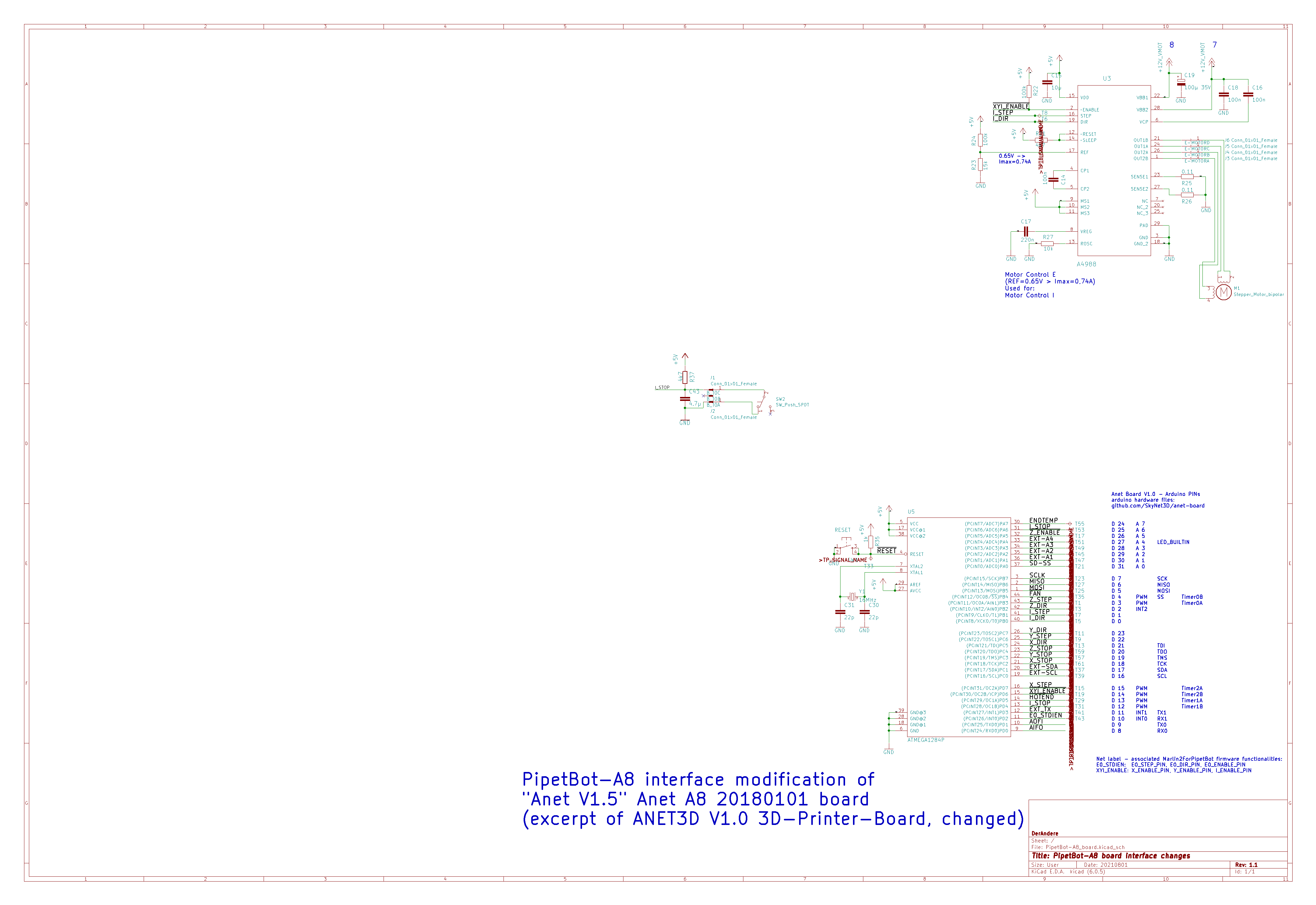
Figure 1: Excerpt from the schematic circuit diagram of the PipetBot-A8 electronics showing modifications of the ANET V1.0 (“ANET V1.5”) board. When compared to the complete schematic circuit diagram for the original ANET V1.0 (“ANET V1.5”) board, the changed net labels reflect the new functionalities associated with the microcontroller pins. The KiCAD EESchema Schematic file (PipetBot-A8_schematic.sch) can be obtained from the PipetBot-A8 repository Copyright 2021 DerAndere. This image is licensed under the terms of the Creative Commons Attribution 4.0 International license (CC BY 4.0).
I installed a pipette tip connector at the extruder platform and then attached a silicone tubing (hose with 1mm inner diameter) between the upper opening of the pipette tip connector and the pump.
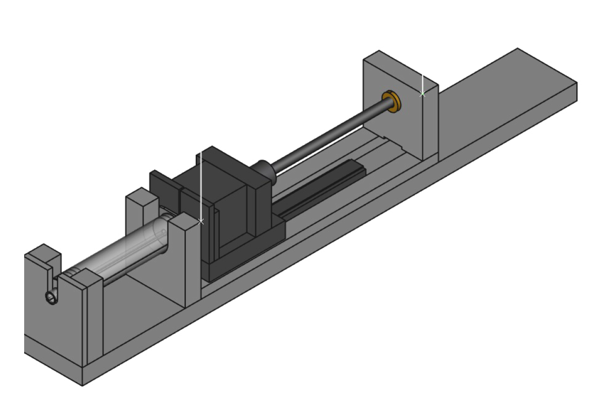
Figure 2: Rendered image of the pipetting module “Pump-AA” for my pipetting robot, the PipetBot-A8. CAD files can be obtained from the project page. Copyright 2019 DerAndere. This image is licensed under the terms of the Creative Commons Attribution 4.0 International license (CC BY 4.0).
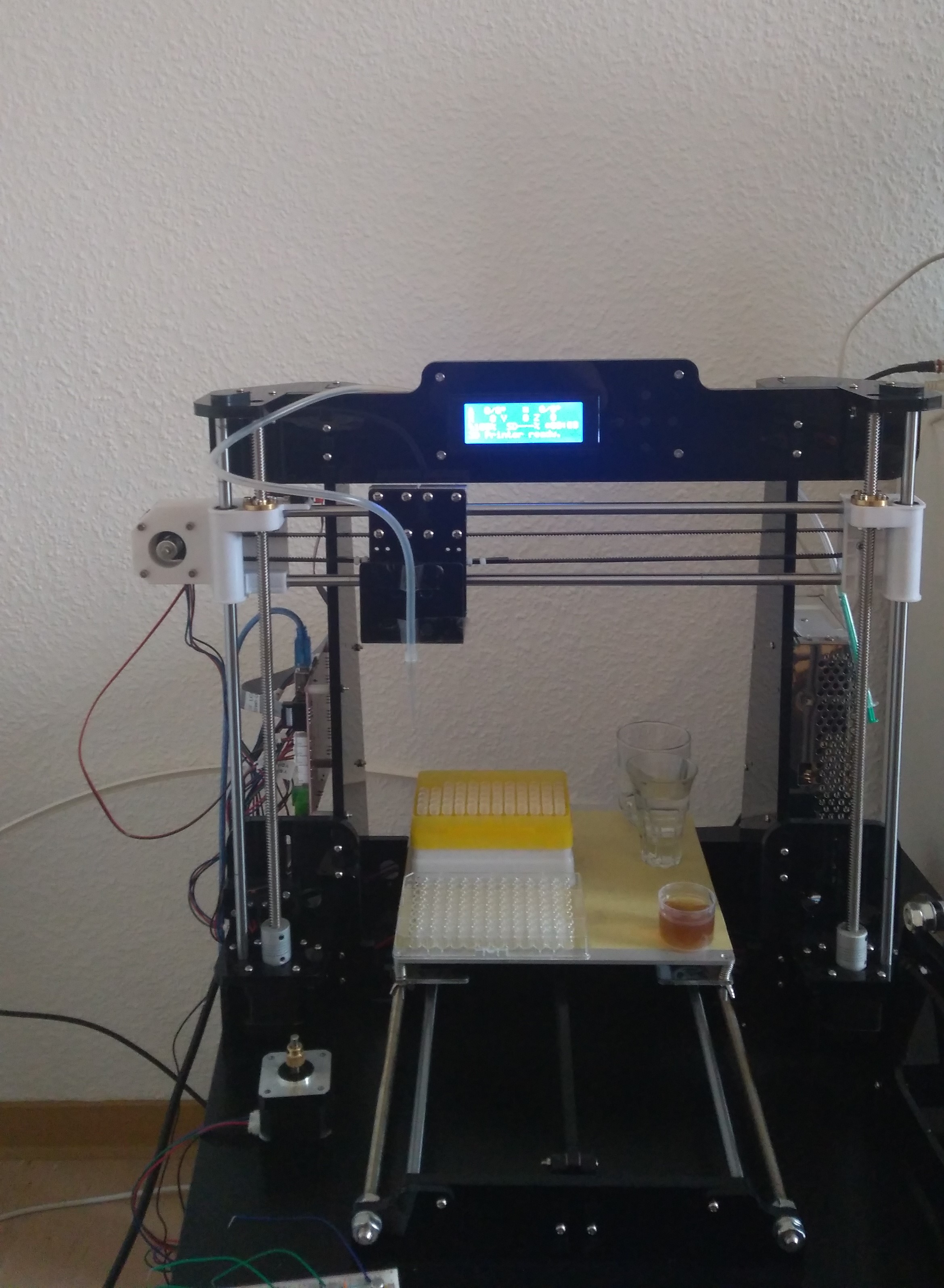
Figure 3: PipetBot-A8 in development. Pipette tip conntector and syringe pump is still missing, but controlling the motors works as expected. Copyright 2018 DerAndere. This image is licensed under the terms of the Creative Commons Attribution 4.0 International license (CC BY 4.0).
The DIY syringe pump prototype is driven by passion (i.e. the extruder motor of the Anet-A8), was made with love from advanced composite material (actually just medium-density fibreboard), processed using next generation ultra precision manufacturing techniques such as our patented HyperFin method (a sharp saw and sandpaper in the hands of an experienced carpenter) and nano-coated for the perfect finish (meaning ABS edgeband glued to the contact surfaces)… Sorry, no fancy plasma cutting / Micro laser metal wire deposition) yet.
Programming the PipetBot-A8 using G-code
The software Printrun is an open source alternative to Repetier Host. It is used for manual and scripted control of cartesian robots, 3D printers and CNC mills. Set up a new device inside the software and set the parameters as follows:
baud rate: 115200.
Filament diameter: 1mm per step for each 1 uL volume per step as determined for the syringe pump.
maximum feed rates for the X-, Y, and Z axis (mm / min): 24000, 24000, 480 maximum extrusion speed (mm / s): 40.
Maximum dimension for the X, Y and Z direction (mm): 220, 220, 240
Distance from left (mm): 30
Distance from front (mm): 20
Homing position for the X-, Y- and Z-axis: -30/-20/0
After the USB serial connection has been established, the device can be is connected within Repetier Host. Warning: It is important to always left-click the button for homing all axis or send the command G28 after the printer was connected before proceeding. Thereafter, one can control the device manually, via single G-code commands. For programming the device, a G-code script has to be written. This can be done by clicking Printing preview > Edit G-code. The integrated G-code editor has syntax highlighting (in the editor view, click on the G-code-syntax tab). Scripts can be saved as a text file with the gcode file extension. Existing scripts can be loaded by clicking File > Load. The Script is sent to the connected device and executed after clicking Print Preview > print or “start print”. The trajectories of the tool specified by a given G-code script can be visualized in an interactive 3D-model of the device in Repetier Host by activating the option “Show Travel Moves” in the Print Preview tab.
The most important G-code commands are:
; Starts a comment that ends at the next line break
%
…
% Starts and ends a program block.
Onnnn Specify a program name (nnnn is a sequence number)
G90 Set to absolute positioning (default)
G91 Set to relative positioning
G1 Xnnn Ynnn Znnn Unnn Fnnn Move the tool to the specified positions in
mm. If previously, the command G91 was given with no G90 before the G1
command, the G1 command specifies the distance in mm the tool should
move in the X-, Y- and Y Axis relative to the current position. Options
left out means no change.
The optional Unnn moves the motor that is used for the
the syringe pump which is connected to the E-motor connector of the Anet
V1.0 board.
The rational number (float) nnn specifies the position/distance
values in mm.
The parameter F specifies the feedrate in mm/min. For moves involving the
XYZ axes, it is the speed along the XYZ path.
For moves involving only the U axis, it is the speed of the syringe plunger in mm/min.
G4 Pnnnn Wait. The integer nnnn specifies the time period in
milliseconds
G4 Snnn: Wait. The integer nnn specifies the time in seconds
G28 Homing of all axes
M280 P0 Snnn For nnn < 200: Move servo with servo index 0 for the
specified angle in degrees. For nnn > 200: Move servo 0 with specified
pulse width in microseconds.
Extending the Anet A8-based liquid handling robot with additional periphery
In most cases, the installation of Marlin2ForPipetBot instead of stock Marlin firmware will free enough pins to add hardware extensions such as servos and sensors to make the robot react on sensor input.
Additionally, the status of all pins but sensitive (protected as per Marlin/src/Marlin.cpp) ones can be changed using the G-code command M42P<pin> S<value> with <value> = 0 or with <value> = 1.
To further extend the possibilities of the cartesian robot, an auxiliary microcontroler could communicate with the main controller board via I2C.
A slower solution is to use Repetier Server with G-code that contains a command with syntax ;@execute command param1 param2. Here, “command” has to be the absolute path to the executable file. It can be used to start an executable file. The executable file can be a python script that uses pySerial or pyFirmata to receive data from- and send commands to another Arduino or a sketch using the boost/asio library. Repetier Server 0.9 supports the Klipper 0.70 firmware which relies on sending of G-code via serial port and pySerial for comparison of data streams. https://forum.repetier.com/discussion/4795/connect-repetier-server-to-klipper-firmware.
Developing GGCGen, a lab robot control software with graphical user interface in Python with wxPython
Although cartesian robots such as liquid handling robots, 3D printers, laser engravers and CNC mills can be programmed by writing G-code scripts, this solution is inconvenient for non-experts.
GGCGen – A Graphical G-code Generator and lab robot control software is a convenient open source control software that I wrote in Python 3. It uses the library wxPython to provide a grafical user interface (GUI). Its backend, pyotronext is based on “mecode” and is responsible for establishing a serial connection to the robot, for converting Python method blocks to G-code and sending the G-code commands to the robot. This allows usage of Python program flow control statements (if conditionals) and for-loops in the scripts and therefore it is possible to make the robot react on input (e.g from sensors like cameras).
In the figures below you can see screenshots of GGCGen running under Microsoft Windows 10 64 bit:
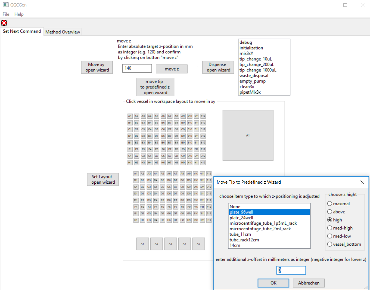
Figure 3: Main frame of the Graphical G-code Generator (GGCGen) with a dialog for user input opened. Copyright 2018 DerAndere. This image is licensed under the terms of the Creative Commons Attribution 4.0 International license (CC BY 4.0).
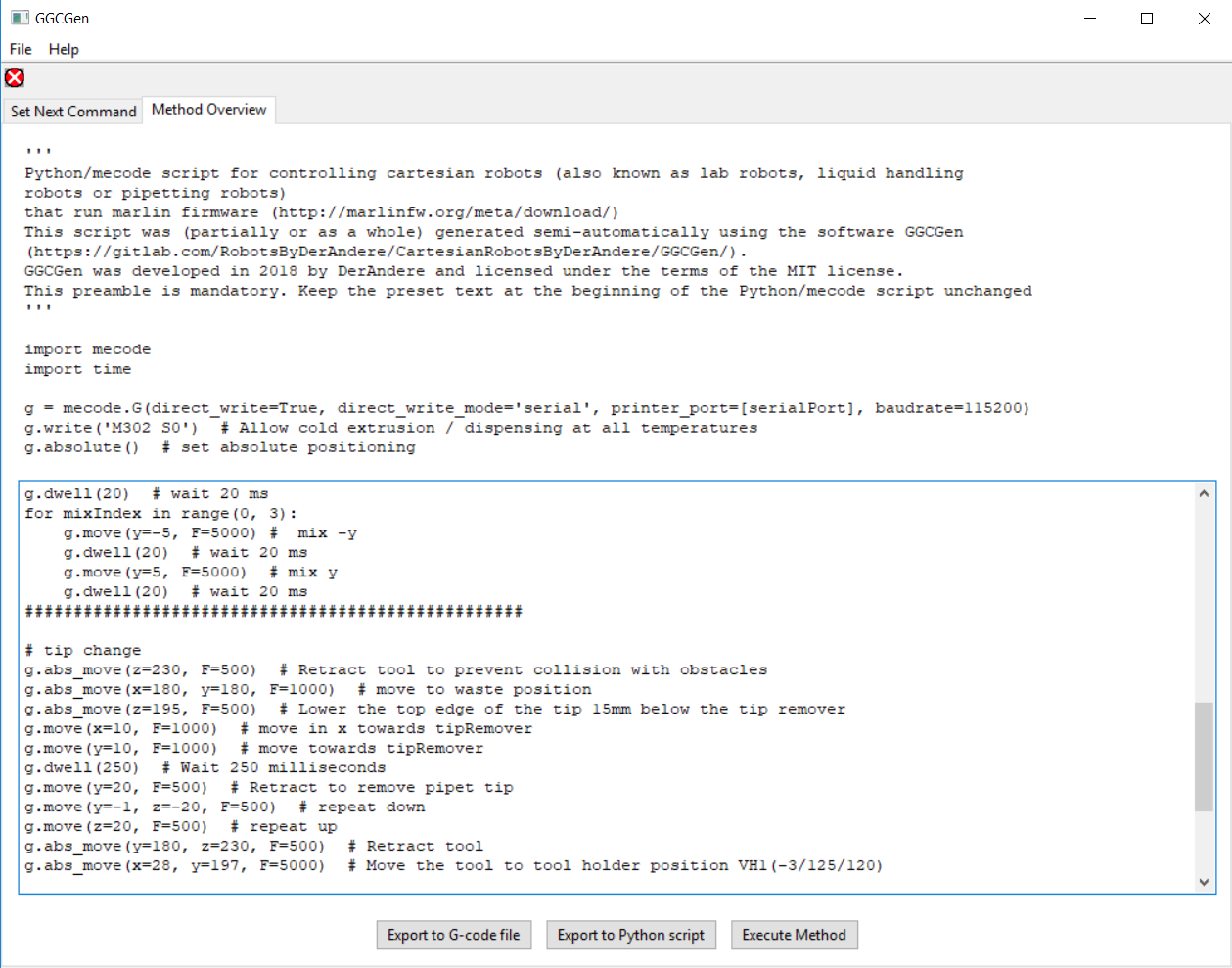
Figure 4: Tab “G-code file export” of GGCGen. Copyright 2018 DerAndere. This image is licensed under the terms of the Creative Commons Attribution 4.0 International license (CC BY 4.0).
To make my programs compatible with the opentrons API v2, it is essential to understand the opentrons python API v2 documentation as well as the code structure of the Opentrons/opentrons repository: Opentrons G-codes and connections are defined in the drivers package. The Hardware representation is the Controler class in its own module. the user only comes in contact with the function protocol_api.execute.get_protocol_api(). It establishes a connection to the robot via the protocol_api.ProtocolContext. The hardware config (more info is available) is a separate module. An instance of the API class from the module hardware_control can be controlled via the opentrons server which is instantiated in the entry point, the main() loop in main.py .labware is defined in a separate module depending on the labware definitions. labware library allows writing ptocols in JSON format (see protocol designer). For running JSON protocols, and labware calibration, the Server of the OT 2 desktop app uses the shared data directory as a resource of config data. Deck slots are defined there as well as labware. What is needed is an opentrons fork with instructions how to find and modify the config files or load other than default config files.
The Opentrons software framework is influenced by the former cloud lab service provider Transcriptic and their autoprotocol JSON format and autoprotocol-python, so both formats are very similar. In future work, the tinylab compiler could be modified to export opentrons protocols. The tinylab project by Alex Carlin developed an open source lab robot that is controlled by protocols written in the autoprotol format. It includes Python code for a proof-of-concept translator / “compiler” to convert autoprotocol into G-code. This code could be used as a basis to add JSON support to pyotronext. Then one could use it as a backend for wet lab accelerator by Bates and others at Autodesk Inc., an open-source GUI for creation of autoprotocol JSON files. Otprotocol is a python library for conversion of protocols written using the opentrons OTone APIv1 to autoprotocol.
Further Reading
You can get detailed information about my DIY lab robot PipetBot-A8 from the resources below:
PipetBot-A8 hardware specification, 3D models (CAD files): DerAndere / PipetBot-A8
Marlin2ForPipetBot firmware: DerAndere1 / Marlin2ForPipetBot
GGCGen - robot control software with graphical user interface (GUI) : DerAndere / GGCGen
pyotronext - opentrons-compatible robot control software backend: DerAndere / pyotronext
Where is this work used?
The following is a list of projects that are based on Multi-axis-Marlin (derived work, based on the work done for the PipetBot-A8 project):
- MarlinFirmware/Marlin: My 6-axis-Marlin merged with official MarlinFirmware/Marlin, https://github.com/MarlinFirmware/Marlin
- D. Vadivel, D.S. Branciforti, O. Kerroumi, M. Dondi, D. Dondi (2022). Mostly 3D printed chemical synthesis robot, HardwareX, 11, e00310.
- FOAMCUTTER_XYUV: My Marlin kinematics option for a 4 axis hot wire foam cutter, co-developed with Olivier Briand (“hobiseven”) and rcKeith: https://github.com/rcKeith/Marlin
- Marlin_9axis_OpenPnP by paloky: 6-axis-Marlin further extended to 9 axes for the OpenPnP project, an open source SMT pick-and-place robot: https://github.com/paloky/Marlin_9axis_OpenPnP
- lumenPnP by Stephen Hawes of opulo (previously index-machines): The commerialized open source SMT Pick-and-Place robot “index” by Stephen Hawes, based on Multi-axis-Marlin and OpenPnP: https://www.opulo.io/products/lumenpnp, https://github.com/sphawes/index, https://github.com/opulo-inc/lumenpnp, https://www.hackster.io/news/index-pnp-machine-can-control-up-to-30-component-feeders-at-the-same-time-20af2e651116
- Fork of Marlin2ForPipetBot for a fly monitoring robot by Daniele Dondi: https://github.com/Daniele-Dondi/Marlin
- SAFE_BED_LEVELING_POSITION_X: My Marlin option for the 7 axis 3D printer by HendrikJan-5D from Hcc!3d https://3d.hcc.nl/139-7-axis-5d-printer.html
- sixi3 by Dave Royer (“i-make-robots”) of Marginallyclever Robots, Ltd.: A commercialized open source robot arm with six degrees of freedom (6 DOF) that runs Multi-axis-Marlin: https://www.marginallyclever.com/products/sixi-3-robot-arm-diy-kit/, https://github.com/MarginallyClever/Marlin-polargraph/tree/sixi3
- 5D printer by HendrikJan K (HendrikJan-5D) of 3d.hcc.nl: 7 axis 3D printer by HendrikJan K (HendrikJan-5D)
- Candy Claw by Chris Riley of Chris’s Basement: Candy claw machine for ERRF 2022, running Marlin configured for 4 axes
- openPnP-octopus by Murray Henwood: Marlin firmware configured for another Pick-and-Place machine with BIGTREETECH Octopus board
- J. M. MacEachern (2022). Theory, Design, and Development of an Open-Source 3D Printed Peristaltic Pump for Microfluidics Applications. Master Thesis. University of Alaska Fairbanks., https://www.reddit.com/r/functionalprint/comments/hsevpl/opensource_multichannel_microfluidicsosmm_pump/, https://github.com/joshmaceachern/OSMMPump/blob/master/README.md.
Related work
Other approaches for lab robot control include:
- List of Lists by Brown (here): outputs an executable opentrons protocol as a python script and an autoprotocol JSON file.
- liquidhandler by dwinters42: python library that uses wxPython for its GUI
- Evobliss software. See Faina et al., 2016 and Faina et al. 2020. Integrates machine vision and machine learning and allows the robot to react to camera input.
- PaR-PaR: See Linshiz et al. 2013. A High level programming language for lab automation which lacks support for conditions and feedback, however.
- Roboliq. See Whitehead et al. 2018: A promising framework for decentralized lab automation.
- Kitson et al. (2016): A 3D printer running Marlin with separate, closed source syringe pump controllers.
- Juan Manuel Parrilla Gutiérrez (2012). Automatic Liquid Handling for Artificial Life Research. A lab robot based on a 3D printer that drives syringes using hobby servos.
- OTTO liquid handler. See David Florian et al. (2020). Lab robot based on Opentrons OT-1 hardware design.
- GentLab OTTObot. Opentrons OT-1 clone by Michele S. Wiseman.
- Multi-axis CNC firmware: LinuxCNC, the successor of the NIST RS274NGC interpreter, version 3, including the NIST EMC controller, g2, grblHAL.
- MPCNC Tangential Knife. Marlin-driven MPCNC tangential knife cutter using gcodetools as CAM software / G-code generator.
Copyright 2017 - 2023 DerAndere