Programming microcontrollers
Here you can follow my progress in programming microcontrollers.
Contents
1 Microcontrollers, development boards, Arduino - what is it?
1.1 Microcontrollers and electric circuits: a customized starter kit
2 Using Sloeber and Bio7 / Eclipse for physical programming in C++
2.1 Installation of the Sloeber plugin
2.2 Creation of a new “Arduino Sketch” project
2.3 Local debugging and unit testing of code for microcontrollers
2.4 AVR Plugin for Eclipse, AVR toolchain and AVRDUDE
2.4.1 Setup of the AVR Plugin for Eclipse
2.4.2 Using the AVR Plugin with libraries
3 My first project: Knitting images - computerizing knitting machines using the AYAB hack
3.1 Computer-controlled knitting of Rib Jacquard using the AYAB hack
4 My second project: DIY MIDI-controller by DerAndere
4.1 Building the DIY MIDI-controller by DerAndere: The circuit
4.2 Programming the DIY-MIDI-controller by DerAndere
5 Microcontrollers and object oriented programming
5.1 Modular programming: Header file, source file and #include “Headerfile.h”
5.2 Use and creation of custom libraries
Microcontrollers, development boards, Arduino - what is it?
[Werbung ohne Auftrag / unpaid advertisement]
Microcontroller units (MCU) integrate the calculation power of a CPU with a clock, EEPROM and memory, inputs, outputs in one chip. For prototyping, development boards with a microcontroller at their heart are available. They make soldering obsolete by adding sockets, peripherals and security measures (e.g. voltage regulators and optocouplers) to the pins of the microchip. The standard for simple tasks is a 8 bit MCU. The Arduino UNO became a very popular development board because the schematics are open-source and it was designed for ease of use. The Arduino UNO Rev.3 features a Microchip Atmega328P 8bit microcontroller clocked at 16 MHz with a preloaded Arduino bootloader, as well as a Microchip ATmega16U2 microcontroller with a preloaded Device Firmware Update (DFU) bootloader and the Arduino USB-to-Serial firmware for ATmega16U2 that enables USB-to-Serial conversion (serial communication via USB1.0 (used a virtual serial port) and programming of the Atmega328P via USB. The Atmega328 microcontroller can be programmed by uploading custom firmware via USB or via inter system programming (ISP). The firmware (“sketch”) can be written in Assembler, C (ANSI-C, ISO/IEC 9899:1990 and parts of C99 with compiler extensions, compare with the Rationale for International Standard— Programming Languages— C, ISO WG14 Document Number N897 and the latest C99 standard with technical corrigendum 3, ISO/IEC 9899:1999 Cor. 3:2007(E) - The latest publicly available draft of the C99 standard with corrigenda is WG14 Document Number N1256 from 2007) or C++17 (ISO/IEC 14882:2017, see publicly available working draft: Document Number N4659 by the ISO/IEC JTC1 (Joint Technical Committee 1) / SC22 (Subcommittee 22) / WG21 (Working Group 21)). Be aware of the limitation, that the AVR-GCC 7.3.0 C compiler avr-gcc.exe does not fully support C99: there is no ISO/IEC 9899:1990- and ANSI/IEEE Std 754-1985 / IEC 60559:1989-compliant double prescission floating point arithmetic and complex types and missing implementation of standard pragmas for AVR-gcc with AVR-libC. When avr-gcc 10.1.0 by Zak Kemble is used as the commpiler, double precision floating point arithmetic is available. Information about supported features are given in the avr-gcc wiki
For C++, with Arduino Uno board definitions up to version 1.8.2, the C++ library ArduinoSTL (a port of uClib++ that can be installed using the library manager of the IDE) can be used. When the library ArduinoSTL is used, most of the C++ Standard Library and thus most of C++11 is supported. The following features are not supported:
-
- next, prev permutations
- functionals
- locales (unsupported on purpose)
- exception handling using the commands try{}, throw{} and catch{}.
When avr-gcc 10.1.0 by Zak Kemble is used, most of C++17 can be used.
AVRDUDE is a command line interface for uploading compiled and linked programs (via USB and other connections) to Microchip Atmel AVR MCUs using ISP. It was created by Brian S. Dean and is now part of the open source AVR-toolchain WinAVR, as well as the AVR-toolchain by Microchip / Atmel. Hernando Barragán developed the open source development platform Wiring with the Wiring library and the USB development board “Wiring board” during his Master’s thesis at Interactive Design Institute Ivrea under the supervision by Massimo Banzi and Casay Reas. The Wiring libraries provide a high level hardware abstraction layer (HAL) on top of the avr/io.h C++ library by Microchip Atmel and uses an API that closely mimicked the API of Reas’ programming language Processing. In 2005, Wiring 0002 was available for download from http://www.wiring.org.co. Between 2008 and 2010, the source code repository was at http://wiring.uniandes.edu.co/source/trunk/wiring/ .
After David Mellis had ported Wiring to the cheaper Atmel Atmega8 in 2005 (arduino/Wiring.h) as part of the project “Music for everyone” during the physicalcomputing course “Strangely Familiar: Unusual Objects for Everyday Life” that was taught by Massimo Banzi and others at Interaction-Ivrea, Banzi and Reas combined their own simple Processing integrated development environment (IDE) with Mellis’ port of the Wiring library to form the Arduino IDE. They founded Arduino Inc. and made more affordable USB development boards that come with a DFU bootloader burned into a USB-to-Serial bridge chip. Together with the adapted Processing IDE (called Arduino IDE) and resources that document the Wiring API (called the “Arduino language reference”) and it’s application, the Arduino framework became popular.
A cheaper alternative is the mbed ecosystem. For projects that require more periphery and calculation power, 32 bit microcontrollers are a better choice. The Teensy 3.6 comes with a 12 bit Digital-Analog converter (DAC) and 10 bit ADC and supports many libraries, including an advanced audio library with a graphical user interface that enables additive- and wavetable sound synthesis. The Arduino Due and cheaper Arduino Due compatible boards provide similar periphery and come with USB2.0 functionality that is capable of high speed USB (480 Mbit/s) in device mode and host mode. If more flexibility and speed for bigger projects is needed, one should consider using an FPGA alongside- or instead of a microcontroller. Big FPGAs are built around a CPU and/or can be programmed to contain softcores (integrated microcontrollers made from the logic gates of the FPGA).
Microcontrollers and electric circuits: a customized starter kit
You may consider the following items for your customized starter kit:
Using Sloeber and Bio7 / Eclipse for physical programming in C++
In my opinion, physical programming in C++ is a great way to get to know the principles of programming. There are many practical example projects available online that make use of the Arduino Uno or compatible development boards to which programs written in C++ (with some restrictions, see section 1) can be uploaded. Most importantly you get instant real-world feedback from your program when you upload it to the microcontroller device. If you want to learn programming or test your code, you can use simulator software where you can build a virtual circuit including a microcontroller device, load your code and simulate the program execution. Autodesk circuits feature of the tinkercad online tool by Autodesk (tinkercad.com) contains a digital circuit simulator that supports a virtual Arduino Uno Rev.3 development board building block that can be integrated into virtual circuits. The Arduino Simulator 1.5 by Xevro.be is a standalone program for offline-use and available for free. Similarly, Proteus is commercially available from labcenter.com and contains a more sophisticated simulator that makes use of Splice models of various microcontrollers.
Installation of the Sloeber plugin
The Sloeber product bundle for physical programming of microcontroller devices is easy to install. Under Microsoft Windows you simply have to unpack the downloaded folder and move the folder “sloeber” directly to the system partition to do so. For Bio7, move the folder into the folder Bio7/plugins or install the plugin via the Eclipse marketplace client or via Help Install New Software. On computers with Microsoft Windows as the operating system, it comes with MinGW which provides the GNU compiler collection (gcc) and the GNU Debugger (GDB). Depending on the system, the environment variables might have to be edited to add MinGW and the gcc.exe, eclipse and Sloeber to the system Path. Start Eclipse with the sloeber add-on by double clicking the file sloeber.exe in the folder sloeber or by double-clicking a short-cut to the Bio7.exe. In the Eclipse menu select Windows -> preferences -> C/C++ -> file types -> new and enter *.ino as filename and C++ source file as type and click “Apply”. In Bio7, the same menu entry can be found by clicking Preferences -> Preferences -> ….
In addition, inside Bio7/Eclipse, specify the path the executable file MinGW.exe in the menu Preferences -> Preferences -> C/C++ -> Build -> Environment -> Add. In the text field for the variable, type “PATH” (without “”), in the text field for the value, type the path to the executable files mingw32-c++.exe, mingw32-g++.exe, mingw32-gcc and gdb.exe, in my case “C:/Bio7/arduinoPlugin/packages/Jantje/tools/MinGW/5.3.0” (without “”) and click “Apply”.
Creation of a new “Arduino Sketch” project
Go to Preferences -> Arduino and add folders with private libraries and hardware definitions. In Preferences -> Arduino -> LibraryManager you can add online libraries, in Platforms and Boards, you can add board definitions and Platforms. Select the following boards:
Arduino -> Arduino AVR boards as well as all boards from the folder Jantje.
If you want to use the hardware abstraction layer of the Arduino IDE within Eclipse, add the following code at the top of the project main fileProjectname.ino: (compare section 5.2):
#include <Arduino.h>
This line of code includes the standard library Arduino.h which declares several methods that are frequently used. it replaces (includes) the following headers from the C standard library
#include <stdlib.h>
#include <string.h>
#include <math.h>
#include <avr/interrupt.h>
#include "wiring.h"

#ifdef __cplusplus
#include "HardwareSerial.h"
#endif
As soon as a program is complete and does not contain any syntax error, it can be verified and then compiled. In the Sloeber toolbar, first click on verify, then click on upload sketch and choose the option to build before uploading. During compilation, the compiler creates a program in machine code that is executable by hardware. Sloeber uses the AVR-GCC toolchain which includes the GNU compiler collection (GCC, consisting of the GNU C compiler (gcc) and the GNU C++ compiler (g++)) for translation of the C/C++ code into machine language that is executable by the Atmel AVR chips, as well as the programmer AVRDUDE for uploading scripts onto the Atmel AVR chip. If files with the file extension .ino are compiled using Sloeber (or the Arduino IDE), header files (.h) and a source file (main.cpp) with the code main(void) {init(); setup(); for(;;) loop(); return 0} is added to the main.cpp file before compilation.
I recommend to have a look the following online libraries that are supported by Sloeber: Encoder, ArduinoJSON, CaptureTimer, Gaussian, HardWire, LinkedList, OctoPrintAPI, TMRpcm, CONNECTIONS -> Adafruit_mp3, ArduinoFFT, Neurona, Plotter, pRNG, RAMP, DEVICE CONTROL -> absmouse, AccelStepper, Brushless Servo, Dynamixel_Servo, EEPROMextend, Firmata, FirstBuild – Relay, MIDIUSB, Mouse, MP3Player, PWMServo, Relay, Servo, Stepper, StepperControl, XYZrobotServo, OTHER -> PlotPlus, Voltage Reference, SIGNAL INPUT/OUTPUT -> FreqCount, FreqMeasure, HalfStepper, MorePins, Pin, ResponsiveAnalgRead, RotaryEncoder, SmoothADC, SoftPWM.
Local debugging and unit testing of code for microcontrollers
If you are new to coding, consider skipping this chapter for now and continue reading below. Based on a tutorial for an older version of Sloeber I found out how to perform software debugging code for compatible microcontrollers locally on a personal computer. The instructions for unit testing are based on this tutorial and included in square brackets, if deviating. A more advanced tutorial can be found on http://mitchtronic.blogspot.com/2017/03/setting-up-google-test-google-mock.html . Unit tests can be used in test-driven development (test-first development) to prevent both, bugs and bad code structure.
1) For unit testing, make sure that under Preferences -> Preferences -> Arduino the library gtest is installed (see paragraph 3). In the project explorer, rightclick on the Project and from the context menu choose Import -> Import Arduino libraries into the current project -> gtest. (Alternative: Arduino -> Add a library to the current project -> gtest). Right-click on the project and left-click New -> Source file. Keep the project name as the source folder, enter a name, e.g. projectnamegtest.cpp and enter at least the following code:
// Do not remove the include below
#ifdef UNITTEST
#include "gtest.h"
#include "projectname.h"

// Enter your tests here using the command
// TEST(testname, state) {
// …
// EXPECT_EQ (variable, expectvalue);
// }

#endif
2) In the project explorer, rightclick on the Project and from the context menu choose Properties -> Arduino -> Manage configurations -> New). Enter the name of the debug configuration (e.g. {“LocalDebug”} [“UnitTest”]). Keep the default options (copy settings from: existing configuration: Release) and leftclick OK.
3) Leftclick the newly created configuration and leftclick Set Active.
4) Leftclick Verify/Compile
5) For the setting Configuation, choose the newly created configuration from the dropdown menu and for the setting platform folder, select …/packages/Jantje/hardware/pc/1.0.2. Select the correct board, e.g. Arduino Uno and the upload protocol Default and for the setting Debug or unit test, select {“Debug”} [“unit test”] from the dropdown menu and leftclick “Apply and Close”.
6) Leftclick Verify/Compile in the Sloeber toolbar.
7) In the toolbar on top, leftclick the tool “Launch configuration” to choose “New Launch configuration” from the dropdown menu. Choose Launch Mode {“Debug”} [“Run”] and Launch Configuration Type {“C/C++ Application”} [C/C++ Unit] -> Next. Browse for the correct project. Change the {C/C++ Application to LocalDebug\<Projectname>.exe} [C/C++ Unit to UnitTest\<Projectname>.exe] where <ProjectName> is the name of the project. For the setting “Build Configuration” choose {“LocalDebug”} [“UnitTest”] from the dropdown list and left-click OK. In the Toolbar at the top leftclick the tool “launch mode” to select {“Debug”} [“Run”] from the dropdown menu. From the toolbar at the top leftclick “build”. From the toolbar at the top leftclick {“Launch in debug mode”} [“Launch in Run mode”].
(or: rightclick on the project and in the context menu left-click {“Debug as” -> “Debug configurations …-> C/C++ Application -> … (see above) -> Debug} [“Run as” ->Run configurations … -> C/C++ Unit -> … (see above) -> Run])
8) Change to the debug perspective. Leftclick to the left of a line in the code to set a breakpoint, e.g. at the first line of the code. Then Debug the code. In the debug toolbar at the top, leftclick on the tool “resume”, “step into” (go through the code instructions by instruction), “strep over” (to step over debugged procedures) etc. View variables and disassembly code to find bugs that produce unexpected behaviour. Leftclick “Terminate” and then “Stop” in the toolbars at the top. Then change back to the Arduino perspective, rightclick on the project and in the context menu leftclick Build Configurations -> Set Active -> Release. Then in the Sloeber toolbar leftclick “Verify/compile”.
If the debugging / unit test run is aborted due to an error, try the following: a) In the Arduino perspective Leftclick Arduino -> Reattach libraries b) Rightclick on the project and from the context menu leftclick Index -> Re-resolve unresoved includes. c) Restart Bio7/Eclipse.
Now let’s consider the following code example:
The file blink.h:
 /*
 * blink.h
 *
 *  Created on: Nov 27, 2015
 *      Author: jan
 */

#ifndef BLINK_H_
#define BLINK_H_
#include "Arduino.h"
#define INTERVAL 500 //The blinking interval

uint8_t calcLedState(uint32_t currentMillis, uint8_t ledState);


#endif /* BLINK_H_ */

//Added by Sloeber
#pragma once
The file blink.cpp
 /*
 * blink.cpp
 *
 *  Created on: Nov 27, 2015
 *      Author: jan
 */

#include "blink.h"
#include "Arduino.h"

void setup() {
       pinMode(LED_BUILTIN, OUTPUT);
}

void loop() {
       static uint8_t ledState = LOW;
       ledState = calcLedState(millis(), ledState);
       digitalWrite(LED_BUILTIN, ledState);
}

uint8_t calcLedState(uint32_t currentMillis, uint8_t ledState) {
       static uint32_t previousMillis = 0;
       if (currentMillis - previousMillis >= INTERVAL) {
             previousMillis = currentMillis;

             if (ledState == LOW)
                    return HIGH;
             else
                    return LOW;
       }
       return ledState;
}
For the files above, the unit test file would be called e.g. blinkgtest.cpp . It could contain the following code:
 #ifdef UNITTEST
#include "gtest.h" // Provides methods for unit tests including TEST()
                   // and EXPECT_EQ()
#include "blink.h"

TEST(blink, start) {
       EXPECT_EQ(HIGH, calcLedState(0, HIGH));
       EXPECT_EQ(LOW, calcLedState(0, LOW));
       EXPECT_EQ(HIGH, calcLedState(1, HIGH));
       EXPECT_EQ(LOW, calcLedState(1, LOW));
//     EXPECT_EQ(2, calcLedState(INTERVAL-2, HIGH));
//     EXPECT_EQ(2, calcLedState(INTERVAL-1, HIGH));
//     EXPECT_EQ(2, calcLedState(INTERVAL, HIGH));
//     EXPECT_EQ(2, calcLedState(INTERVAL+1, HIGH));
//     EXPECT_EQ(2, calcLedState(INTERVAL+2, HIGH));

}

TEST(blink, on) {
       uint32_t mill=0;
       for (mill = 0; mill < INTERVAL; mill++) {
             EXPECT_EQ(HIGH, calcLedState(mill, HIGH)) << mill;
       }
       EXPECT_EQ(LOW, calcLedState(INTERVAL, HIGH)) << INTERVAL;

}

TEST(blink, off) {
       uint32_t mill=0;
       for (mill = 0; mill < INTERVAL; mill++) {
             EXPECT_EQ(LOW, calcLedState(INTERVAL+mill, LOW)) << INTERVAL+mill;
       }
       EXPECT_EQ(HIGH, calcLedState(2*INTERVAL, LOW)) << INTERVAL;
}

#endif
In the code above, a local variable with scope limited to the loop() function was declared using the keyword static.
Citing the ISO document number N4296 (Working Draft, Standard for Programming Language C++) which later became ISO/IEC 14882:2014 (most relevant to users of AVR-GCC 7.3.0, but officially replaced by ISO/IEC 14882:2017): “1. All variables which do not have dynamic storage duration, do not have thread storage duration, and are not local have static storage duration. The storage for these entities shall last for the duration of the program (3.6.2, 3.6.3). […]. 3. The keyword static can be used to declare a local variable with static storage duration. […] 4. The keyword static applied to a class data member in a class definition gives the data member static storage duration.” (ISO document number N4296 (draft of the C++ standard ISO/IEC 14882:2014), §3.7.1 Static storage duration.) And:
“Destructors (12.4) for initialized objects (that is, objects whose lifetime (3.8) has begun) with static storage duration are called as a result of returning from main and as a result of calling std::exit (18.5).” (ISO document number N4296 (draft of the C++ standard ISO/IEC 14882:2014), §3.6.3
Termination.)
This means, the value assigned to variables declared with the keyword static is stored until either return 0; (preferred) or std::exit(); is called from the body of the main() function, which is called by the setup() function of the Arduino core and which closes the program. Even if the local scope is exited because the function ends and the same function with that local static variables is called again later, the static variables remain accessible under their original identifier from within that function.
More in depth debugging can be done with Atmel Studio 7 by Microchip Inc. which comes with a simulator for several Microcontrollers: https://www.youtube.com/watch?v=tScXBU5VFDo .
AVR Plugin for Eclipse, AVR toolchain and AVRDUDE
while the Eclipse plugin Sloeber installs the suboptimally designed Arduino IDE and while using PlatformIO means installing a separate IDE, the AVR Plugin for Bio7 2.9 / Eclipse 4.9 in conjugation with the plain AVR toolchain comes without ovearhead. The downside is, that the setup is more difficult:
Setup of the AVR Plugin for Eclipse
-
Install mingw-w64. Edit the system variables to add the directories …/mingw-w64/mingw-w64/bin and …/mingw-w64/mingw-w64/x86_64-w64-mingw32/bin to the beginning of the system path.
-
Install the AVR toolchain. For Microsoft Windows 64bit, I recommend the updated AVR toolchain avr-gcc-7.3.0-x64-mingw which can be downloaded as a .7zip archive from
https://forum.arduino.cc/index.php?topic=556557.0 and extracted using 7zip. Move the contained folder avr-gcc-7.3.0-x64-mingw to the system partition. Duplicate the file mingw32-make.exe and rename the copy make.exe. Edit the system variables to add the directories …/avr-gcc-7.3.0-x64-mingw/bin and …/ avr-gcc-7.3.0-x64-mingw/avr/bin to the system path after …/mingw-w64/mingw-w64/x86_64-w64-mingw32/bin.
-
Install and run the freeware Zadig, use it to install libusb / WinUSB.
-
If problems with avrdude.exe occur, search your computer for a libusb0_x86.dll in a folder with a name ending with x86. Copy that file to the Windows directory in your system partition. Rename that file to libusb0.dll
-
Install AVRDude-mingw32 in the folder …/avr-gcc-7.3.0-x64-mingw/bin
-
Download the AVR Plugin 2.4.2 or newer as a .zip archive, open Bio7 2.9 / Eclipse 4.9 left-click Help -> Install new software” -> Add -> Archive and select the .zip Archive to install the plugin. The AVR Plugin is not well configured: Always change the optimization level for the debug build configuration to “Slight Optimizations (-O1)”: For each project that was set up using the AVR plug-in and that has a Debug build configuration, right-click the project and in the context menu that appears, left-click Preferences -> AVR and activate “Enable individual settings for build configurations”
-
Preferences -> AVR -> AVRDude and activate the option “Use custom configuration file for AVRDude” and set AVRDude config file: …\avr-gcc-7.3.0-x64-mingw\bin\avrdude.conf . Left-click “Apply an Close”
-
Right-click the project and in the context menu that appears left-click Properties -> C/C++ Build -> Settings -> Tool Settings -> AVR C++ Compiler -> Optimization. Select Configuration: “Debug” and then select Optimization Level: “Slight Optimizations (-O1)”. Left-click “Apply and Finish”.
-
In Bio7 / Eclipse, go to Preferences -> AVR -> Paths and for each entry, select “custom” from the drop down menu. Specify the path of the …/ avr-gcc-7.3.0-x64-mingw/bin/ directory for all entries, except for AVR header files where you have to specify the /avr-gcc-7.3.0-x64-mingw/bin/ directory in the directory of the AVR toolchain and except for the Atmel Part Description Files where no value has to be entered.
-
Left-click Preferences -> AVR
-
If you want to use Arduino libraries, you have several options:
-
Download LoseAVR from https://forum.arduino.cc/index.php?topic=556557.0 and extract the .7zip archive using 7zip. Use the included precompiled static Arduino libraries in the ArduinoCore subfolder.
-
Or precompile the Arduino libraries as static libraries yourself:
-
retrieve the folder ArduinoCore-avr/tree/master/cores/arduino of the ArduinoCore-avr repository either by downloading and extracting the repository or by using git fork / clone the repository.
-
Instructions for Global AVR Configuration (section 2.3.5) and Software Organisation (section 3) using the AVR Plugin are available online. Follow until (including) section 3.1 and click on the compile errors that occur during the build process. Replace the indicated occurences of <Arduino.h> with “Arduino.h” and replace <IPadress.h> with “IPAddress.h”, then repeat until the build process is successful without errors.
-
Copy the files Arduino.h, HardwareSerial.h and binary.h to the folder ArduinoCore/ArduinoUnoRev3_Release
-
Right-click the Project “ArduinoCore” and in the context-menu that appears left-click “Refresh (F5)”. Now the folder ArduinoCore/ArduinoUnoRev3_Release should contain the fikes Arduino.h, HardwareSerial.h, binary.h, libArduinoCore.a and the subdirectory src/Arduino which contains all relevant object (.o) files
-
While following the instructions of section 3.2, create a new C++ project for each extra library (e.g. ArduinoServo) and only import the desired library (excluding example folders and other utility folders that depend on that library) and do not import the Arduino core or Arduino variants:
-
Do not import the Arduino core files or variants files to the extra-library’s project. In the extra-libraries’ project properties, when adding paths and symbols, only add the project’s src folder and any subfolders from the working directory.
-
Then right-click the extra-library project and in the context menu that appears left-click Properties -> C/C++ General -> Add. Select “Add to all languages” and then left-click “File System” -> “browse”. Select the Arduino core directory on your computer (not in the Bio7 / Eclipse working space)
-
and repeat the previous step in order to add the Arduino/variants/standard folder to the project’s path.
-
build the project.
-
Copy the file Servo.h to the folder ArduinoServo/ArduinoUnoRev3_Release and add a new folder ArduinoServo/ArduinoUnoRev3_Release/src/arduino to which the contents of the Arduino core library have to be copied.
-
In the Bio7 / Eclipse program directory there should be now some lib[extralibraryname].a archive file in the extra-library’s project folder (e.g. …/workingspace/ArduinoServo/ArduinoUnoRev3_Release/libArduinoServo.a) next to the extra-librarie’s header (.h) file as well as folders containing the relevant object (.o) files and the sorce-code of the arduino core library.
-
-
-
Copy the respective modules into your project and compile everything together
-
Use a link to the local Arduino core directory to the project:
-
Right-click on the project and in the context menu that appears left-click Properties -> C/C++ General -> Paths and Symbols -> Source Location -> Link folder -> Advanced. Select “Link to folder in the File System”, set Folder name: Arduino. Left-click “Browse” and navigate to the directory of the Arduino core library (folder “arduino” containing the Arduino.h and other files). Left-click “Ok”
-
Right-click on the project and in the context menu that appears left-click Properties -> C/C++ General -> Paths and Symbols -> Includes -> Add -> Workspace. Select the folder <projectname>/arduino of the current project. Select “Add to all configurations” and “Add to all languages”. Left-click “OK”
-
Left-click Add -> Filesystem and navigate to the directory …hardware/arduino/variants/standard . Select “Add to all configurations” and “Add to all languages” and left-click “OK”. Left-click “Apply and close”
-
-
Alternatively, do the following:
-
Downlod the base makefile from https://gist.github.com/entrity/5424505 and specify the correct paths for each of the …DIR variables. E.g. ARDDIR = <my Arduino folder> is the folder with the subfolder /hardware/arduino/cores/arduino
-
In Bio7 / Eclipse, create a new C++ project with a project-specific makefile:
-
-
# This is the name of the file that shall be created. (It is also the name of my primary source file, without the file extension.)
TARGET = temp

# create a variable that only pertains to this project
MY_OWN_LIBRARY_DIR = /usr/home/MJ/Arduino/libraries/mj_midi

# "EXTRAINCDIRS" is a variable used by the base makefile. The base makefile creates a -I compiler flag for every item in the "EXTRAINCDIRS" list.
EXTRAINCDIRS = $(MY_OWN_LIBRARY_DIR)

# specify *.c source files pertaining to my project
SRC =

# specify *.cpp source files pertaining to my project
PSRC = temp.cpp $(MY_OWN_LIBRARY_DIR)/midi-listener.cpp $(MY_OWN_LIBRARY_DIR)/midi-song.cpp

# specify additional (non-core) Arduino libraries to include
ARDLIBS = SoftwareSerial

# include my base makefile
include /d/dev/avr/Makefile.base
Using the AVR Plugin with libraries
The precompiled libraries generated using option a) in section 2.4.1 can be used in the following way:
-
Create a new C++ project and select AVR appication.
-
Add a source folder src
-
Add a source file src/main.cpp
-
Add code to the src/main.cpp. You can add the following minimum example to src/main.cpp for testing the AVR plugin (uncomment for serial communication):
 /**
 * @title: Eclipse AVR Plugin test without serial communication
 * @author: DerAndere
 * @year: 2018
 * // Copyright 2018 DerAndere
 * // SPDX-License-Identifier: MIT
 * @license: MIT
 * @about: using https://github.com/zkemble/millis
 */

#include <avr/io.h>
#include <util/delay.h>
//#include "Arduino.h" // Arduino core library. License: LGPL 2.1 or later
#include "Servo.h" // Arduino Servo library. License: LGPL 2.1 or later
#include "millis.h" // https://github.com/zkemble/millis . License: MIT
#include <avr/interrupt.h>

#ifndef F_CPU
#define F_CPU 16000000UL
#endif // F_CPU


static const int delayms = 500;
static const int servo1Pin = 12; // PB4 is servo1Pin
Servo servo1;

int main(void){
       millis_init();     // setup millis() timers. Always the first thing in main().

       PORTB &= ~_BV(PB5); // set pin PB5 (digital pin 13 with
                                       // built-in LED) = 0 (low) by clearing
                                       // bit PB5 of register PORTB (for
                                       // register PORTB clear bit PB5 = 0:
                                       // Negated (bitwise not) setting of bit
                                       // PB5=1 (_BV(PB5) means bitwise right
                                       // shifting (1<<PB5)) bitwise
                                       // and-equals register PORTB)
       DDRB |= _BV(PB5);  // set pin PB5 (digital pin 13 with
                                       // built in LED) as digital output by
                                       // setting bit PB5 of the data
                                       // direction register for port B (for
                                       // register DDRB5 set bit PB5)

//       Serial.begin(9600); // baudrate = 9600
       servo1.attach(servo1Pin);        // set digital pin 12
                                       // (ATmega328P pin PB4) as servo1Pin


       sei();                    // enable interrupts

       millis_t lastChangedLEDms = 0; // when timing starts, counter starts at 0


       for (;;) {
             millis_t currentms = millis();

             // Has it been 500ms since last change for LED1?
             if(currentms - lastChangedLEDms >= 500)
             PORTB ^= _BV(PB5); // toggle built-in LED at pin 13 on/off by
                                              // toggling pin PB5 (digital pin
                                              // 13 with built-in LED) between 0
                                              // (low) and 1 (high) by toggling
                                              // (bitwise XOR-equal) bit PB5 of
                                              // the register PORTB between 0
                                              // (low) and 1 (high)
             servo1.write(200);
//             Serial.print("Hello");

             // Store time
             lastChangedLEDms = currentms;
             _delay_ms(delayms);

       }
       return 0;
}
With serial communication:
 /**
 * @title: Eclipse AVR Plugin test with serial communication
 * @author: DerAndere
 * @year: 2018
 * // Copyright 2018 DerAndere
 * // SPDX-License-Identifier: MIT
 * @license: MIT
 */

#include <avr/io.h>
#include <util/delay.h>
#include "Arduino.h" // Arduino core library. License: LGPL 2.1 or later
#include "Servo.h" // Arduino Servo library. License: LGPL 2.1 or later
//#include "millis.h" // https://github.com/zkemble/millis . License: MIT
#include <avr/interrupt.h>

#ifndef F_CPU
#define F_CPU 16000000UL
#endif // F_CPU


static const int delayms = 500;
static const int servo1Pin = 12; // PB4 is servo1Pin
Servo servo1;

int main(void){
       init();      // initialize timers and enable interrupts. See
                    // https://github.com/arduino/ArduinoCore-
                    // avr/blob/master/cores/arduino/wiring.c

       PORTB &= ~_BV(PB5); // set pin PB5 (digital pin 13 with
                                       // built-in LED) = 0 (low) by clearing
                                       // bit PB5 of register PORTB (for
                                        // register PORTB clear bit PB5 = 0:
                                       // Negated (bitwise not) setting of bit
                                       // PB5=1 (_BV(PB5) means bitwise right
                                       // shifting (1<<PB5)) bitwise
                                       // and-equals register PORTB)
       DDRB |= _BV(PB5);  // set pin PB5 (digital pin 13 with
                                       // built in LED) as digital output by
                                       // setting bit PB5 of the data
                                       // direction register for port B (for
                                       // register DDRB5 set bit PB5)

uint32_t lastChangedLEDms = 0; // when timing starts, counter starts at 0

       Serial.begin(9600); // baudrate = 9600
       servo1.attach(servo1Pin); // set digital pin 12
                                 // (ATmega328P pin PB4) as servo1Pin

       sei();                    // enable interrupts


       for (;;) {
             uint32_t currentms = millis();

             // Has it been 500ms since last change for LED1?
             if(currentms - lastChangedLEDms >= 500)
             PORTB ^= _BV(PB5); // toggle built-in LED at pin 13 on/off by
                                 // toggling pin PB5 (digital pin
                                 // 13 with built-in LED) between 0
                                 // (low) and 1 (high) by toggling
                                 // (bitwise XOR-equal) bit PB5 of
                                 // the register PORTB between 0
                                 // (low) and 1 (high)
             servo1.write(200);
             Serial.print("Hello");

             // Store time
             lastChangedLEDms = currentms;
             _delay_ms(delayms);

       }
       return 0;
}
- For each uncompiled library (e.g. the one that was precompiled by you
according to section 2.4.1 above and that is
#included in your project, do the following: Left-cick C/C++ Build -> Settings -> AVR C++ Linker. To the list Libraries (-l), add an entry, e.g. “ArduinoCore” (including “”) and to the list Libraries Path (-L), add an entry and navigate to the path to the folder in which the file libArduinoCore.a was saved (see final step of option a) in section 2.4.1).
If that library relies on the Arduino core, right-click the project and in the context menu left-click Properties -> C/C++ General -> Paths and Symbols -> Add -> File System. Browse for the Arduino cores/arduino. Select “Add to all languages”. Left-click Apply. Repeat this for the path variants/Standard. Left-click “Apply and Close”.
-
Left-click on the project and in the AVR Plugin toolbar left-click “build”.
-
Then in the AVR Plugin toolbar left-click “Upload current project to Atmel target MCU (Ctrl + Alt + U)”
My first project: Knitting images - computerizing knitting machines using the AYAB hack
[Werbung ohne Auftrag / unpaid advertisement]
A vendor at the marketplace Etsy, called redpinkgreen, ships the All Yarns Are Beautiful (AYAB) shield kit version 1.3 for 37,40 €. It is a DIY self-soldering kit for an extension shield that fits on an Arduino UNO compatible development board and provides an interface to control Brother / Jones & Brother / KnitKing / CompuKnit / Defendi / Topical / Electroknit knitting machines from a personal computer via USB. The shield of the All Yarns Are Beautiful (AYAB) Project was developed by Christian Obersteiner (chris007), Andreas Müller (Andz), Sebastian Oliva, and Christian Gerbrandt (derchris) from the Chaos Computer Club München. They also developed the AYAB software for Windows, Linux and MacOS. which has to be downloaded from https://ayab-knitting.com/ayab-software/ and installed as described at documentation -> quick start on the AYAB project homepage. This software provides a graphical user interface for uploading of image files from the computer to the Arduino-compatible development board / microcontroller device. The AYAB software as well as schematics and EAGLE files for the AYAB shield are open source. An instruction how to assemble the shield is available from the AYAB project homepage. A video tutorial for connecting the AYAB shield with the knitting machine can be found, too. I used it to hack a Brother Electroknit KH 910 (equal to KnitKing CompuKnit II). I highly recommend to also change the old capacitors of the power supply of the knitting machine. I am not the first one who experienced the old capacitors being destroyed after powering on the knitting machine. In order to prevent further damage of the knitting machine, you can purchase replacement capacitors from redpinkgreen at Etsy or from a vendor called kadash24 at ebay. The parts to be replaced are two safety capaciors of class X, subclass X2 (and optionally a spare miniature fuse according to DIN 41 571, medium time-lag, 5 x 20 mm, glass tube, rated voltage: 250 V, rated current: 500 mA): (according to IEC 60-384-14) with a rated voltage of at least 275V (AC) and with a capacitance of 0.1µF and 0.047µF, respectively:
- RIFA PME 271 M 610, IEC climate code: 40/085/58 GPC, capacitance: 0.1µF, safety code: (a)X, resonance frequency: f0 = 4.9 MHz, rated voltage: 275 V (AC), certified voltage: 250V~MP. Replace with KEMET PME271M610MR30 or KEMET P276CE104M275
- RIFA PME 271 M 547, IEC climate code: 40/085/56 GPC, capacitance: 0.047 µF, safety class: (a)X, resonance frequency: f0 = 7.0 MHz, rated voltage: 275 V (AC), certified voltage: 250V~MP. Replace with KEMET PME271M547MR30 or KEMET P276QL473M275
- FSP-Püschel miniature fuse, 5 x 20 mm, glass tube, rated voltage 250 V, rated current: 500 mA
Replacing the capacitors is easy: Unplug the knitting machine, remove the batteries, unfasten the 5 rightmost screws on the top of the Brother KH 910 (2 at the rear, 3 at the needle bed) and remove the 3 small round plastic pins that hold the right part of the cover in place. Remove the printed circuit board of the power supply, unsolder the two old capacitors and connect the new ones to the respective holes of the printed circuit board using through-hole-soldering techniques and a solder iron tip temperature of 385 °C for max. 3 seconds.
Computer-controlled knitting of Rib Jacquard using the AYAB hack
As a showcase for the AYAB hack, I decided to knit textiles that have colour-patterns and a pleasant back-side without floating threads: Rib Jacquard. I used a Brother Electroknit KH 910 electronic knitting machine (equal to KnitKing CompuKnit II; see manual for KH 910) with the Brother KR 850 ribber (see manual for KR 850) and a colour changer for double bed knitting machines by Brother (e.g. KRC 900). The procedure for an older version of the AYAB software is explained in a series of videos on youtube (part 1, 2, 3, 4). I contributed to the AYAB manual where detailed instructions can be found. I also made a tutorial that shows how to do textile design with open source software. The video can be found in this post
My second project: DIY MIDI-controller by DerAndere
My second project related to pragramming and electronics is a MIDI-controller based on an Arduino UNO-compatible development board. I took inspiration from Goetz Mueller-Duerholt’s MIDI-Controller (here and here). Similar projects are here and here.
Building the DIY MIDI-controller by DerAndere: The circuit
The following schematic circuit diagram was created using the free version of EAGLE by Autodesk Inc. with the Adafruit EAGLE library.
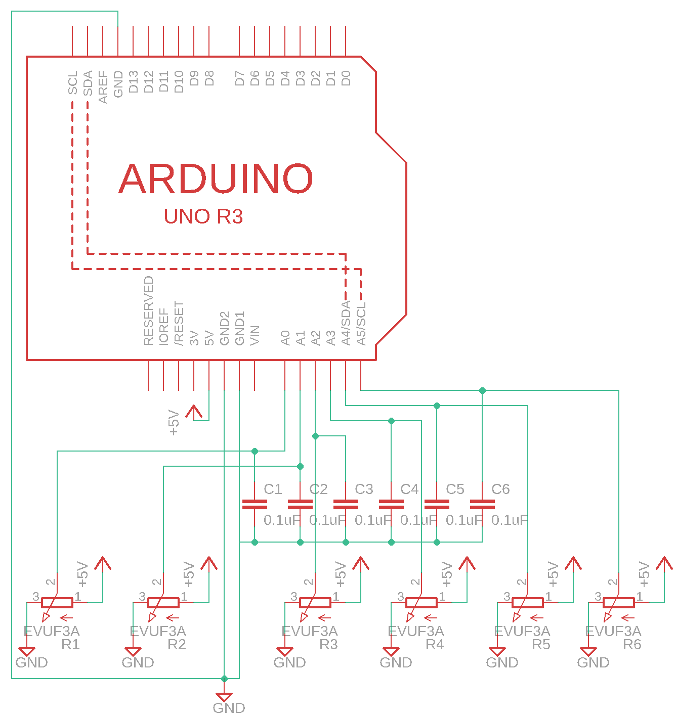
Fig. 1: Schematic circuit diagram for the MIDI controller by DerAndere. Created using the free version of EAGLE by Autodesk Inc with the Adafruit EAGLE library. Arduino UNO R3 can be replaced with any compatible development board. The potentiometers R1-R6 have 10 kOhm nominal resistance and linear taper. I chose vertical rotary potentiometers with 16 mm shaft and DIP terminals for through-hole soldering or use with solder-less breadboards. Copyright 2018 DerAndere. Image is licensed under the terms of the Creative Commons Attribution 4.0 International license (CC BY 4.0).
The potentiometers R1-R6 have 10 kOhm resistance and linear taper. I chose vertical rotary potentiometers with 16 mm shaft and DIP terminals for through-hole soldering or use with solder-less breadboards such as Alpha RV0600DF-43 (Mono) or Alpha RV16AD1F-41 by Taiwan Alpha Electronic Inc., Ltd. They are distributed by www.musikding.de.
Programming the DIY-MIDI-controller by DerAndere
In Bio7 / Eclipse with the Sloeber plug-in, left-click File -> New. Type the name of the project, e.g. ArduinoMIDIcontroller. Left-click “finish”.
Below is the complete Program code for the files ArduinoMIDIcontroller/ArduinoMIDIcontroller.h and ArduinoMIDIcontroller/ArduinoMIDIcontroller.cpp (change .cpp to .ino file extension (for compatibility with original Arduino IDE):
 /**
 * @title: ArduinoMIDIcontroller.h
 * @version: 4.0
 * @reference: This code is derived work from code for a MIDI controller from
 * https://goetzmd.de/tontechnik/ab-damit-auf-die-lochraster-platine#more-1021
 * (Copyright 2015 Götz Müller-Dürholt; adapted with significant changes by
 * DerAndere).
 * @author: DerAndere
 * @created: 2018
 * Copyright 2018 DerAndere
 * This code is protected by copyright. You are not allowed to
 * redistribute this code or derived work without explicit approval by
 * Götz Müller-Dürholt and the author of this derived work (DerAndere).
 * Downloading and copying the code or parts of it is only allowed for private,
 * non-commercial use.
 * @info: https://derandere.gitlab.io/physical-programming/
 * @language: C++ for AVR-GCC
 * @description: Sketch for an Arduino Uno Rev.3 or a compatible development
 * board that is used inside the DIY-MIDI-controller by DerAndere. Based on
 * ideas from [https://goo.gl/I1ipZj](https://goo.gl/I1ipZj) and
 * https://goetzmd.de/tontechnik/ab-damit-auf-die-lochraster-platine#more-1021
 * (Copyright 2015 Götz Müller-Dürholt)
 */

/** include Arduino.h standard library header that provides functions to use
 * with Arduino/Genuino-compatible development boards or Atmel microprocessors
 */
#include "Arduino.h"

/**
 * declare and define / initialize constexpr for count of analog pins
 * to which potis are connected. Uncomment if you want to use this instead of ccCount
 */
// constexpr uint8_t analogPinCount = 6;

/**
 * define / initialize array containing the selected MIDI controller
 * numbers
 */
uint8_t midiCCselect[] = { 22, 23, 24, 25, 26, 27 };

// declare and define byte for the count of MIDI controller messages to be sent
const int8_t ccCount = sizeof(midiCCselect) / sizeof(int8_t);

/**
 * declare byte for ControlChange command (176 for
 * sending on MIDI channel 1)
 */
extern uint8_t controlChange;

/**
 * declare array for Pin numbers of Pins
 * to which potis are connected
 */
extern uint8_t analogPin[ccCount];

/**
 * declare array for the selected MIDI controller
 * numbers
 */
extern uint8_t midiCCselect[ccCount];

// declare variables and arrays with size equal to count of potis
extern int analogVal[ccCount];
extern int potiVal[ccCount];
extern int8_t controllerVal[ccCount];
extern int8_t controllerValPrevious[ccCount];
extern uint32_t midiSendTime;
extern uint32_t midiSendTimePrevious;


// declare function prototypes

/**
 * newmap Funktion by Bill Perry aka bperrybap.
 * @reference:
 * https://forum.arduino.cc/index.php?topic=417690.msg2877460#msg2877460
 * Copyright 2015 Bill Perry.
 * @license: Creative Commons Attribution ShareAlike 3.0 (CC-BY-SA-3.0).
 * @param: long x = raw input value
 * @param: long in_min = minimum of possible raw input range
 * @param: long in_max = maximum of possible raw input range
 * @param: long out_min = minimum of possible scaled output range
 * @param: long out_min = maximum of possible scaled output range
 * @return: long (out_min – out_max)
 * @fn: maps in equal intervals (using linear interpolation) as opposed to
 * flawed map() function from the Arduino.h library.
 */
long newmap(const long /* x */, const long /* in_min */, const long& /* in_max */,
             const long /* out_min */, const long /* out_max */);

// Function for sending a MIDI command:
void sendMIDI(uint8_t /* statusByte */, uint8_t /* dataByte1 */,
              uint8_t /* dataByte2 */);

/**
 * @fn: Smoothes values depending on the smoothingFactor.
 * @param: valLast = last value from reading an analog pin.
 * @param: analogPinNum = pin to be read
 * @param: smoothingFactor between 0 (none, fast) and 99 (maximum, slow)
 * @returns: int
 */
int smoothRead(const int valLast, const int8_t analogPinNum,
             const uint8_t& smoothingFactor);


/**
 * define / initialize byte for ControlChange command (176 for
 * sending on MIDI channel 1)
 */
uint8_t controlChange = 176;

/**
 * define / initialize array containing Pin numbers of Pins
 * to which potis are connected
 */
uint8_t analogPin[] = { 0, 1, 2, 3, 4, 5 };

// define / initialize variables and arrays with size equal to count of potis
int analogVal[ccCount] = { 0 };
int potiVal[ccCount] = { 0 };
int8_t controllerVal[ccCount] = { 0 };
int8_t controllerValPrevious[ccCount] = { 0 };
uint32_t midiSendTime = (uint32_t) 0;
uint32_t midiSendTimePrevious = (uint32_t) 0;


/**
 * newmap Funktion by Bill Perry aka bperrybap.
 * @reference:
 * http://forum.arduino.cc/index.php?topic=417690.msg2877460#msg2877460
 * Copyright 2015 Bill Perry.
 * @license: Creative Commons Attribution ShareAlike 3.0 (CC-BY-SA-3.0).
 * @param: long x = raw input value
 * @param: long in_min = minimum of possible raw input range
 * @param: long in_max = maximum of possible raw input range
 * @param: long out_min = minimum of possible scaled output range
 * @param: long out_min = maximum of possible scaled output range
 * @return: long (out_min – out_max)
 * @fn: maps in equal intervals (using linear interpolation) as opposed to
 * flawed map() function from the Arduino.h library.
 */
long newmap(const long x, const long in_min, const long& in_max,
             const long out_min, const long out_max)
             {
       if (x == in_max)
             return out_max;
       else if (out_min < out_max)
             return (x - in_min) * (out_max - out_min + 1) / (in_max - in_min)
                          + out_min;
       else
             return (x - in_min) * (out_max - out_min - 1) / (in_max - in_min)
                          + out_min;
}

// Function for sending a MIDI command:
void sendMIDI(uint8_t statusByte, uint8_t dataByte1, uint8_t dataByte2) {
       Serial.write(statusByte);
       Serial.write(dataByte1);
       Serial.write(dataByte2);
}

/**
 * @fn: Smoothes values depending on the smoothingFactor.
 * @param: valLast = last value from reading an analog pin.
 * @param: analogPinNum = pin to be read
 * @param: smoothingFactor between 0 (none, fast) and 99 (maximum, slow)
 * @returns: int
 */
int smoothRead(const int valLast, const int8_t analogPinNum,
             const uint8_t& smoothingFactor) {
       return (long) smoothingFactor * (long) valLast / 100L
                    + (100L - (long) smoothingFactor / 100L) *
                    analogRead(analogPinNum);
}

void setup() {
       Serial.begin(9600);
}

/**
 * loop goes through indices of the potiVal, successively reads smoothed
 * analog pin values, converts into MIDI-controller values and upon change
 * sends MIDI ControlChange messages
 */
void loop() {
       for (int8_t i = 0; i < ccCount; ++i) {
             midiSendTime = micros();
             if ((midiSendTime - midiSendTimePrevious) >= 100) {
                    potiVal[i] = smoothRead(potiVal[i], analogPin[i], 20);
                    controllerVal[i] = newmap(potiVal[i], 0, 1023, 0, 127);
                    if (controllerVal[i] != controllerValPrevious[i]) {
                          sendMIDI(controlChange, midiCCselect[i], controllerVal[i]);
                          controllerValPrevious[i] = controllerVal[i];
                    }
                    midiSendTimePrevious = midiSendTime;
             }
       }
}
The above C++ code follows the paradigm of procedural programming and could therefore easily be rewritten in AVR-GCC compatible C99 according to the outdated standard ISO/IEC 9899:1999. For the even more outdated C89 dialect, declaration of variables before the loop is required, because in C89, variables can only be declared at the beginning of blocks (inside brackets). For complex programs, it makes sense to follow the principle of modular programming. The above code can also be rewritten following the paradigm of object-oriented programming. The result can be found in section 5.3 below. Be aware of the fact, that classes and implicit passing variables by reference is not possible in C.
Microcontrollers and object oriented programming
Modular programming: Header file, source file and #include “Headerfile.h”
As already seen in the code above (section 4.2), it makes sense to organize program code in a modular manner. This allows for parts of the code to be reused in different applications. Variables and functions that are used several times should be declared in a header file and defined in a source file. The definition includes the code for the implementation.
The header file should be saved under the name CustomLibrary.h (.h is the file extension for header files) and contain the following code including include guides and function declaration for function prototypes:
#ifndef CustomLibrary_H
#define CustomLibrary_H

type func(type paramA, type paramB);

#endif
The source file for the modules should be saved under the file name LibraryModuleAImplementationSource.cpp (.cpp is the file extension for source code files written in C++) and contain the following code:
#include "CustomLibrary.h"

type func(type paramA, type paramB){
  function body (dependent on paramA, paramB)
}
Now all the functions in the CustomLibrary (declared in CustomLibrary.h) can be easily used (“called”) from within any source file that contains the command #include “CustomLibrary.h” at the top. In our example, the function func can be called from within the main program file that includes that header file by adding the following code:
#include "CustomLibrary.h"

type varA = 0;
type varB = 3;
type varC = 4;

void(){
  varA = func(varB, varC);
}
In the above program, varA is initially declared as being a variable of
the given type and immediately defined as being zero. Then varA becomes
overwritten with a value that is the result of func(varB, varC). The
latter means that the first argument of the function func, that is
paramA, is substituted by varB and that the argument paramB is
substituted by varC. From the definition of varB = 3 and varC = 4, varA
is calculated according to the method defined in the function body of
func() in the source file containing the implementation.
For modular programming using Sloeber, right click on the project in the
and click New -> source folder. Give it some name (e.g. src). Right
click on the source folder and click New -> folder. Name the folder
like the module (e.g. ModuleA). Right click on the folder ModuleA and
click New -> *.h file. Give it the same name as the folder with a .h
file extension (ModuleA.h). Then click New -> *.cpp file. Give it the
same name as the folder with a .cpp file extension (ModuleA.cpp). Add
#include <Arduino.h> to all files if not done. Add #include "ModuleA.h"
to the ModuleA.cpp file. Add #include "src/ModuleA/ModuleA.h" to the main program *.h and *.cpp file.
Use and creation of custom libraries
Because of memory restrictions on Arduino/Genuino-compatible development boards, neither the C/C++ standard library nor the standard template library (STL) is included in the Arduino.h standard library. However, the ArduinoSTL library implements the most important features like the advanced containers for this hardware. In order to use libraries, you have to create a folder where such private libraries are to be stored (in a directory with reading- and writing permission). Additionally, this folder has to be specified in Sloeber by clicking preferences -> Arduino -> Add.
Download the latest ArduinoSTL library (a .zip archive can be downloaded from here ) and extract it to your private library folder. Rename the extracted folder to ArduinoSTL. Then, the library can be imported into an existing Arduino Sketch in Sloeber by right-clicking on the project folder in the project manager and clicking Import -> Arduino -> Import Arduino libraries into the current project. In each file that makes use of this library, add the following code:
#include "ArduinoSTL.h"
Refer to the documentation for the chosen library for use and syntax. For examples, use vectors with the following command:
std::vector<T> (n) vectornameA
where T is the type of the vector elements and n is a size_t (unsigned
integer) defining the size of the vector (the total number of elements
in the vector).
std::vector<T> vectornameB {4,5,6,7};
vectornameB.size() gives the size of vector vectornameB as a size_t
(unsigned integer). This can be saved in a variable:
size_t varA = vectornameB.size();
In order to create your own library to make its classes and functions publicly available, refer to the guide
Object oriented programming in modern C++: Code for the MIDI-controller by DerAndere using classes and class inheritance
As a showcase of object oriented programming for microcontrollers usingmodern C++, I chose the code for the MIDI-controller by DerAndere (see section 4.3.2). The sketch can be rewritten in modern C++ as follows. My C++ libraries map2 and ArdUnoRev3API1 have to be installed. Create an Arduino project with a default .cpp file in Bio7/Eclipse CDT with the plug-in Sloeber. Also, download the files of the repository and in Bio7 / Eclipse create a new Project of type Arduino Sketch and import the downloaded files into the project. Alternatively, clone the repository using Bio7 / Eclipse with the plug-in Egit, then open the Git perspective and right-click on the repository and in the context menu left-click Import project. Select “import submodules” and left-click Finish.
Open the Arduino perspective and verify/compile the code using the verify button in the Sloeber toolbar. Then click on the upload button in the Sloeber toolbar and choose the option to build before uploading. The code should compile without error messages.
PWM-based single-wire communication protocol
For a robot that can control servos via pulse width modulation, one can can use the servo pin (e.g pin 27 of the Anet V1.0 board running Marlin-based firmware) can then be connected to a digital input pin of any 5V microcontroller / development board. If the servo pin (pin 27) of the AnetV1.0 board is connected to digital pin 8 of an Arduino UNO Rev.3-compatible development board, several options are available to measure the pulse duration of the servo control signal (duration of the +5V (HIGH) signal output from the servo pin (pin 27) of the Anet V1.0 board). One could use external interrupts (via attach.Interrupt()). Note, that the Arduino docs state: By declaring a variable as volatile, “it directs the compiler to load the variable from RAM and not from a storage register, which is a temporary memory location where program variables are stored and manipulated. […] A variable should be declared volatile whenever its value can be changed by something beyond the control of the code section in which it appears, such as a concurrently executing thread. In the Arduino, the only place that this is likely to occur is in sections of code associated with interrupts, called an interrupt service routine.”
The code on the auxiliary microcontroller could call functions that control servos, motors and other hardware connected to the auxiliary-microcontroller device dependent of the pulse width.
Keep in mind, that bitwise operations in Standard C will automatically promote their operands to an int, which is by default 16 bits in avr-gcc. To work around this use typecasts on the operands, including literals, to declare that the values are to be 8 bit operands. (See section 20 “Why does the compiler compile an 8-bit operation that uses bitwise operators into a 16-bit operation in assembly?” of the FAQ in the avr Libc Reference manual). Also, if clearing interrupt flag registers bits by setting the interrupt flag to logical 1, do not use the bitwise OR equal operator ( |=, pipe equal).
It makes sense to use an interrupt-based version of readPulse. A version using the input capture feature is described here:
https://www.mikrocontroller.net/articles/High-Speed_capture_mit_ATmega_Timer
This is what I came up with.
Notes on programming for embedded systems
floating point arithmetics
When developing software for embedded systems, one must account for the limitations of microcontrollers. Ever since the introduction of Intel’s x87 instruction set extension for the x86 instruction set and its implementation in the 8087 numeric data processor (numeric processor extension for the Intel 8086), computers have hardware floating point units capable of double precision floating point arithmetics that follow the IEEE Standard for Floating-Point Arithmetic (IEEE 754) of 1985. Since introduction of the Intel i486 (80486), the FPU is integrated in CPU chips. However, as of 2022, microcontrollers usually do not have a double precision FPU integrated. 8 bit microcontrollers do not have any FPU integrated, while ARM cortex M4F only has a single precision FPU integrated. Only Arm Cortex M7F has a IEEE 754 compliant double precision FPU integrated. Thus, one should think twice what type to use. With missing hardware FPUs, single precision (float), and especially double precision floating point (double) arithmetic takes many clock cycles in addition to the high memory consumption. Thus, it makes sense to use double only when necessary. Note, that avr-libc implements double as float, which is not IEEE 754 compliant.
#import stdint
double x = 1.0  // double precision
float y = 1.0  // same as 1.0f through implicit casting to float during assignment
double dpResult = (-1.0) * x / 2.0  // -0.5 (uses double precision)
float fResult = (-1.0) * x / 2.0  // -0.5 (uses double precision internally, casts to float aftwerwards)
float fbResult = (-1.0) * y / 2.0  // -0.5 (uses double precision internally, casts to float aftwerwards)
float fcResult = (-1.0f) * x / 2.0f  // -0.5 (uses double precision internally, casts to float aftwerwards)
float spResult = (-1.0f) * y / 2.0f  // -0.5 (uses single precision)
uint64_t u64Result = (-1.0) * x / 2.0  // 0 (dp internally, Cannot store negative values correctly)
uint8_t u8Result = (-1.0) * x / 2.0  // 0 (dp internally, Cannot store negative values correctly)
int64_t i64Result = (-1.0) * x / 2.0  // 0 (dp internally, trunkated)
int8_t i8Result = (-1.0) * x / 2.0  // 0 (dp internally, trunkated)
int8_t i8Result = 1 * (int)x / 2  // 0 (integer arithmetics internally, trunkated)
Enforcing longer types
Because avr-libc implements ints as 16 bit integers, there are cases where you need to force to a longer type, e.g. the expression
1 << 24
i.e. 1 left shifted 24 places is valid on systems with 16 bit ints but invalid on systems with, say, 16 bit ints. Whereas
1L << 24
and for many cases
1UL << 24
is even better because bit manipulations are best done on unsigned types.
Programming frameworks for embedded systems
Because programming microcontrollers requires direct access to the hardware features and those differ between microcontroller models, vendors provide datasheets that document, how to interact with hardware features. On the lowest level, hardware features are usually accessesd via bits in registers. The datasheets provide a the memory map that shows the mapping between memory adresses and hardware features. In addition, the datasheet lists the instruction set for the binary format that can be used to program the MCU. This documentation allows hardware access using machine language (opcode). To allow programming in assembly language (assembler language), an assembler is required that generates machine code. The documentation of the assembler defines the assembly language. Since the 1980s, architectures became standarized and porting assemblers became easier. Since then, vendors release device families that can be programmed with a common instruction set und thus a common assembler. They provide an assembler port for each device family when it is released. Since then, datasheets contain examples in the vendor’s assembler language.
Two assembly sytax styles became the defacto standards: The Intel syntax used in Intel’s documentation of the x86 platform and the AT&T syntax. The AT&T syntax is used by default with the open source GNU compiler collection and its GNU assembler “as”, as well as Clang’s assembler.
To make portability easier, higher level languages are used since more capable 32bit microcontrollers became the norm, the C programming language is commonly used for the mayor parts of the programs (possibly complimented with inline assembler for hardware access that is not supported by the C standard) and compiled to opcode using the vendor’s compiler toolchain (often based on the open source GNU or Clang toolchains). To reduce the amount of inline-assembler for hardware access, vendors today provide a compiler port for each device family. In addition they usually provide device-specific header files that allow hardware access through named variables. At the lowest level, these define names for the memory addresses of each bit of each special purpose register. Today, datasheets use the names defined in these header files to document hardware access and they contain examples written in C with device-specific compiler extensions that use these low-level device-specific header files. The combination of compiler port with compiler extensions and device-specific header files constitutes a framework that provides some kind of abstraction. On top of this, other frameworks can provide higher levels of abstraction that include libraries with commodity functions that make it easier to use complex peripherals in common use cases (abstracion layers 2 and 3). On top of that, some frameworks provide hardware abstaction layers (HAL) for writing code that runs on different device families (abstraction levels 4, 5). Some frameworks contain extra layers of abstraction for platform-independent programming. The most advanced frameworks feature a real-time operating system (abstraction level 6 to 7). The following table gives an overview over the frameworks supported by the development environment PlatformIO:
| Platform | Framework | Language | Abstraction |
|---|---|---|---|
| ESP32 | ESP-NFS | C | 2 |
| ESP32 | Arduino | C++ | 6 |
| AVR | Native (avr-gcc toolchain) | C | 1 |
| AVR | Arduino | C++ | 6 |
| ARM Cortex | CMSIS | C | 2 |
| ARM Cortex | STCube HAL Low Level (LL) driver libraries | C | 3 |
| ARM Cortex | STCube HAL | C | 4 |
| ARM Cortex | libOpenCM | C | 5 |
| ARM Cortex | Arduino | C++ | 6 |
| ARM Cortex | MBED | C++ | 6 |
| ARM Cortex | Zephyr | C++ | 7 |
One of the most important functions is a function that returns elapsed time in milliseconds since program start / reset. The millis function is implemented in the Arduino-core for each platform. On ARM Cortex it is implemented with alias getCurrentMillis() using the STCube HAL functions . There is also an [example that uses a TIM timer peripheral]. Alternative implementations can use other timers. PlatformIO provides an example implementation using STCube Low Level (LL) driver libraries. An implementation using CMSIS-core was provided by github user Ilya ellectroid (“ellectroid”)
/*
* SPDX-License-Identifier: LicenseRef-BSD-3-Clause-STMicroelectronics
* MYHAL.c
* Copyright 2022 DerAndere
* Based on:
* STM32CubeF7 HAL Driver MCU Component (https://github.com/STMicroelectronics/STM32CubeF7/blob/master/Drivers/STM32F7xx_HAL_Driver)
* COPYRIGHT(c) 2015 STMicroelectronics
* Based on stm32f7xx_hal.h (https://github.com/STMicroelectronics/STM32CubeF7/blob/master/Drivers/STM32F7xx_HAL_Driver/Inc/stm32f7xx_hal.h)
* COPYRIGHT(c) 2015 STMicroelectronics
*/
/**
******************************************************************************
* @file stm32f7xx_hal.h
* @author MCD Application Team
* @brief This file contains all the functions prototypes for the HAL
* module driver.
******************************************************************************
* @attention
*
* Copyright (c) 2017 STMicroelectronics.
* All rights reserved.
*
* This software is licensed under terms that can be found in the LICENSE file
* in the root directory of this software component.
* If no LICENSE file comes with this software, it is provided AS-IS.
*
******************************************************************************
*/
/* Define to prevent recursive inclusion -------------------------------------*/
#ifndef __STM32F7xx_HAL_H
#define __STM32F7xx_HAL_H
#ifdef __cplusplus
extern "C" {
#endif
/* Includes ------------------------------------------------------------------*/
#include "stm32f7xx_hal_conf.h"
typedef enum
{
MYHAL_TICK_FREQ_10HZ = 100U,
MYHAL_TICK_FREQ_100HZ = 10U,
MYHAL_TICK_FREQ_1KHZ = 1U,
MYHAL_TICK_FREQ_DEFAULT = MYHAL_TICK_FREQ_1KHZ
} MYHAL_TickFreqTypeDef;
/* Initialization and Configuration functions ******************************/
int MYHAL_Init(void);
int MYHAL_InitTick(uint32_t TickPriority);
/* Exported variables ---------------------------------------------------------*/
/** @addtogroup HAL_Exported_Variables
* @{
*/
extern __IO uint32_t uwTick;
extern uint32_t uwTickPrio;
extern MYHAL_TickFreqTypeDef uwTickFreq;
/* Peripheral Control functions ************************************************/
void MYHAL_IncTick(void);
uint32_t MYHAL_GetTick(void);
#ifdef __cplusplus
}
#endif
#endif /* __STM32F7xx_HAL_H */
/**
* stm32f7xxhal_cortex.h
* SPDX-License-Identifier: LicenseRef-BSD-3-Clause-STMicroelectronics
* Based on:
* stm32f7xx_hal_cortex.h (https://github.com/STMicroelectronics/STM32CubeF7/blob/master/Drivers/STM32F7xx_HAL_Driver/Inc/stm32f7xx_hal_cortex.h)
******************************************************************************
* @file stm32f7xx_hal_cortex.h
* @author MCD Application Team
* @brief Header file of CORTEX HAL module.
******************************************************************************
* @attention
*
* Copyright (c) 2017 STMicroelectronics.
* All rights reserved.
*
* This software is licensed under terms that can be found in the LICENSE file in
* the root directory of this software component.
* If no LICENSE file comes with this software, it is provided AS-IS.
*
******************************************************************************
*/
/** @defgroup CORTEX_Preemption_Priority_Group CORTEX Preemption Priority Group
* @{
*/
#define NVIC_PRIORITYGROUP_0 ((uint32_t)0x00000007U) /*!< 0 bits for pre-emption priority
4 bits for subpriority */
#define NVIC_PRIORITYGROUP_1 ((uint32_t)0x00000006U) /*!< 1 bits for pre-emption priority
3 bits for subpriority */
#define NVIC_PRIORITYGROUP_2 ((uint32_t)0x00000005U) /*!< 2 bits for pre-emption priority
2 bits for subpriority */
#define NVIC_PRIORITYGROUP_3 ((uint32_t)0x00000004U) /*!< 3 bits for pre-emption priority
1 bits for subpriority */
#define NVIC_PRIORITYGROUP_4 ((uint32_t)0x00000003U) /*!< 4 bits for pre-emption priority
0 bits for subpriority */
#ifdef __cplusplus
}
#endif
#endif /* __STM32F7xx_HAL_CORTEX_H */
/**
* stm32f7xx_hal_rcc.h
* SPDX-License-Identifier: LicenseRef-BSD-3-Clause-STMicroelectronics
* Based on:
* stm32f7xx_hal_rcc.h (https://github.com/STMicroelectronics/STM32CubeF7/blob/master/Drivers/STM32F7xx_HAL_Driver/Inc/stm32f7xx_hal_rcc.h)
******************************************************************************
* @file stm32f7xx_hal_rcc.h
* @author MCD Application Team
* @brief Header file of RCC HAL module.
******************************************************************************
* @attention
*
* Copyright (c) 2017 STMicroelectronics.
* All rights reserved.
*
* This software is licensed under terms that can be found in the LICENSE file in
* the root directory of this software component.
* If no LICENSE file comes with this software, it is provided AS-IS.
******************************************************************************
*/
/* Define to prevent recursive inclusion -------------------------------------*/
#ifndef __STM32F7xx_HAL_RCC_H
#define __STM32F7xx_HAL_RCC_H
#ifdef __cplusplus
extern "C" {
#endif
#ifdef __cplusplus
/* Includes ------------------------------------------------------------------*/
#include "stm32f7xx_hal_def.h"
/* Include RCC HAL Extended module */
/* (include on top of file since RCC structures are defined in extended file) */
#include "stm32f7xx_hal_rcc_ex.h"
/** @defgroup RCC_Oscillator_Type Oscillator Type
* @{
*/
#define RCC_OSCILLATORTYPE_NONE ((uint32_t)0x00000000U)
#define RCC_OSCILLATORTYPE_HSE ((uint32_t)0x00000001U)
#define RCC_OSCILLATORTYPE_HSI ((uint32_t)0x00000002U)
#define RCC_OSCILLATORTYPE_LSE ((uint32_t)0x00000004U)
#define RCC_OSCILLATORTYPE_LSI ((uint32_t)0x00000008U)
/**
* @}
*/
/** @defgroup RCC_HSE_Config RCC HSE Config
* @{
*/
#define RCC_HSE_OFF ((uint32_t)0x00000000U)
#define RCC_HSE_ON RCC_CR_HSEON
#define RCC_HSE_BYPASS ((uint32_t)(RCC_CR_HSEBYP | RCC_CR_HSEON))
/**
* @}
*/
/** @defgroup RCC_LSE_Config RCC LSE Config
* @{
*/
#define RCC_LSE_OFF ((uint32_t)0x00000000U)
#define RCC_LSE_ON RCC_BDCR_LSEON
#define RCC_LSE_BYPASS ((uint32_t)(RCC_BDCR_LSEBYP | RCC_BDCR_LSEON))
/**
* @}
*/
/** @defgroup RCC_HSI_Config RCC HSI Config
* @{
*/
#define RCC_HSI_OFF ((uint32_t)0x00000000U)
#define RCC_HSI_ON RCC_CR_HSION
#define RCC_HSICALIBRATION_DEFAULT ((uint32_t)0x10U) /* Default HSI calibration trimming value */
/**
* @}
*/
/** @defgroup RCC_LSI_Config RCC LSI Config
* @{
*/
#define RCC_LSI_OFF ((uint32_t)0x00000000U)
#define RCC_LSI_ON RCC_CSR_LSION
/**
* @}
*/
/** @defgroup RCC_PLL_Config RCC PLL Config
* @{
*/
#define RCC_PLL_NONE ((uint32_t)0x00000000U)
#define RCC_PLL_OFF ((uint32_t)0x00000001U)
#define RCC_PLL_ON ((uint32_t)0x00000002U)
/**
* @}
*/
/** @defgroup RCC_PLLP_Clock_Divider PLLP Clock Divider
* @{
*/
#define RCC_PLLP_DIV2 ((uint32_t)0x00000002U)
#define RCC_PLLP_DIV4 ((uint32_t)0x00000004U)
#define RCC_PLLP_DIV6 ((uint32_t)0x00000006U)
#define RCC_PLLP_DIV8 ((uint32_t)0x00000008U)
/**
* @}
*/
/** @defgroup RCC_PLL_Clock_Source PLL Clock Source
* @{
*/
#define RCC_PLLSOURCE_HSI RCC_PLLCFGR_PLLSRC_HSI
#define RCC_PLLSOURCE_HSE RCC_PLLCFGR_PLLSRC_HSE
/**
* @}
*/
/** @defgroup RCC_System_Clock_Type RCC System Clock Type
* @{
*/
#define RCC_CLOCKTYPE_SYSCLK ((uint32_t)0x00000001U)
#define RCC_CLOCKTYPE_HCLK ((uint32_t)0x00000002U)
#define RCC_CLOCKTYPE_PCLK1 ((uint32_t)0x00000004U)
#define RCC_CLOCKTYPE_PCLK2 ((uint32_t)0x00000008U)
/**
* @}
*/
/** @defgroup RCC_System_Clock_Source RCC System Clock Source
* @{
*/
#define RCC_SYSCLKSOURCE_HSI RCC_CFGR_SW_HSI
#define RCC_SYSCLKSOURCE_HSE RCC_CFGR_SW_HSE
#define RCC_SYSCLKSOURCE_PLLCLK RCC_CFGR_SW_PLL
/**
* @}
*/
/** @defgroup RCC_System_Clock_Source_Status System Clock Source Status
* @{
*/
#define RCC_SYSCLKSOURCE_STATUS_HSI RCC_CFGR_SWS_HSI /*!< HSI used as system clock */
#define RCC_SYSCLKSOURCE_STATUS_HSE RCC_CFGR_SWS_HSE /*!< HSE used as system clock */
#define RCC_SYSCLKSOURCE_STATUS_PLLCLK RCC_CFGR_SWS_PLL /*!< PLL used as system clock */
/**
* @}
*/
/** @defgroup RCC_AHB_Clock_Source RCC AHB Clock Source
* @{
*/
#define RCC_SYSCLK_DIV1 RCC_CFGR_HPRE_DIV1
#define RCC_SYSCLK_DIV2 RCC_CFGR_HPRE_DIV2
#define RCC_SYSCLK_DIV4 RCC_CFGR_HPRE_DIV4
#define RCC_SYSCLK_DIV8 RCC_CFGR_HPRE_DIV8
#define RCC_SYSCLK_DIV16 RCC_CFGR_HPRE_DIV16
#define RCC_SYSCLK_DIV64 RCC_CFGR_HPRE_DIV64
#define RCC_SYSCLK_DIV128 RCC_CFGR_HPRE_DIV128
#define RCC_SYSCLK_DIV256 RCC_CFGR_HPRE_DIV256
#define RCC_SYSCLK_DIV512 RCC_CFGR_HPRE_DIV512
/**
* @}
*/
/** @defgroup RCC_APB1_APB2_Clock_Source RCC APB1/APB2 Clock Source
* @{
*/
#define RCC_HCLK_DIV1 RCC_CFGR_PPRE1_DIV1
#define RCC_HCLK_DIV2 RCC_CFGR_PPRE1_DIV2
#define RCC_HCLK_DIV4 RCC_CFGR_PPRE1_DIV4
#define RCC_HCLK_DIV8 RCC_CFGR_PPRE1_DIV8
#define RCC_HCLK_DIV16 RCC_CFGR_PPRE1_DIV16
/* Flags in the CR register */
#define RCC_FLAG_HSIRDY ((uint8_t)0x21U)
#define RCC_FLAG_HSERDY ((uint8_t)0x31U)
#define RCC_FLAG_PLLRDY ((uint8_t)0x39U)
#define RCC_FLAG_PLLI2SRDY ((uint8_t)0x3BU)
#define RCC_FLAG_PLLSAIRDY ((uint8_t)0x3CU)
/** @brief Macros to enable or disable the main PLL.
* @note After enabling the main PLL, the application software should wait on
* PLLRDY flag to be set indicating that PLL clock is stable and can
* be used as system clock source.
* @note The main PLL can not be disabled if it is used as system clock source
* @note The main PLL is disabled by hardware when entering STOP and STANDBY modes.
*/
#define __MYHAL_RCC_PLL_ENABLE() SET_BIT(RCC->CR, RCC_CR_PLLON)
#define __MYHAL_RCC_PLL_DISABLE() CLEAR_BIT(RCC->CR, RCC_CR_PLLON)
#define __MYHAL_RCC_GET_FLAG(__FLAG__) (((((((__FLAG__) >> 5) == 1)? RCC->CR :((((__FLAG__) >> 5) == 2) ? RCC->BDCR :((((__FLAG__) >> 5) == 3)? RCC->CSR :RCC->CIR))) & ((uint32_t)1 << ((__FLAG__) & RCC_FLAG_MASK)))!= 0)? 1 : 0)
#define HSE_TIMEOUT_VALUE HSE_STARTUP_TIMEOUT
#define HSI_TIMEOUT_VALUE ((uint32_t)2) /* 2 ms */
#define LSI_TIMEOUT_VALUE ((uint32_t)2) /* 2 ms */
#define PLL_TIMEOUT_VALUE ((uint32_t)2) /* 2 ms */
#define CLOCKSWITCH_TIMEOUT_VALUE ((uint32_t)5000) /* 5 s */
#define PLLI2S_TIMEOUT_VALUE 100U /* Timeout value fixed to 100 ms */
#define PLLSAI_TIMEOUT_VALUE 100U /* Timeout value fixed to 100 ms */
/**
******************************************************************************
* @file stm32f7xx_hal_rcc_ex.h
* @author MCD Application Team
* @brief Header file of RCC HAL Extension module.
******************************************************************************
* @attention
*
* Copyright (c) 2017 STMicroelectronics.
* All rights reserved.
*
* This software is licensed under terms that can be found in the LICENSE file in
* the root directory of this software component.
* If no LICENSE file comes with this software, it is provided AS-IS.
******************************************************************************
*/
/* Define to prevent recursive inclusion -------------------------------------*/
#ifndef __STM32F7xx_HAL_RCC_EX_H
#define __STM32F7xx_HAL_RCC_EX_H
#ifdef __cplusplus
extern "C" {
#endif
/* Includes ------------------------------------------------------------------*/
#include "stm32f7xx_hal_def.h"
/*------------------------------- PLL Configuration --------------------------*/
#if defined (STM32F765xx) || defined (STM32F767xx) || defined (STM32F769xx) || defined (STM32F777xx) || defined (STM32F779xx)
#define __MYHAL_RCC_PLL_CONFIG(__RCC_PLLSource__, __PLLM__, __PLLN__, __PLLP__, __PLLQ__,__PLLR__) \
(RCC->PLLCFGR = ((__RCC_PLLSource__) | (__PLLM__) | \
((__PLLN__) << RCC_PLLCFGR_PLLN_Pos) | \
((((__PLLP__) >> 1) -1) << RCC_PLLCFGR_PLLP_Pos) | \
((__PLLQ__) << RCC_PLLCFGR_PLLQ_Pos) | \
((__PLLR__) << RCC_PLLCFGR_PLLR_Pos)))
#else
#define __MYHAL_RCC_PLL_CONFIG(__RCC_PLLSource__, __PLLM__, __PLLN__, __PLLP__, __PLLQ__) \
(RCC->PLLCFGR = (0x20000000 | (__RCC_PLLSource__) | (__PLLM__)| \
((__PLLN__) << RCC_PLLCFGR_PLLN_Pos) | \
((((__PLLP__) >> 1) -1) << RCC_PLLCFGR_PLLP_Pos) | \
((__PLLQ__) << RCC_PLLCFGR_PLLQ_Pos)))
#endif /* STM32F767xx || STM32F769xx || STM32F777xx || STM32F779xx */
#ifdef __cplusplus
}
#endif
#endif /* __STM32F7xx_HAL_RCC_EX_H */
/**
******************************************************************************
* @file stm32f7xx_hal_def.h
* @author MCD Application Team
* @brief This file contains HAL common defines, enumeration, macros and
* structures definitions.
******************************************************************************
* @attention
*
* Copyright (c) 2017 STMicroelectronics.
* All rights reserved.
*
* This software is licensed under terms that can be found in the LICENSE file
* in the root directory of this software component.
* If no LICENSE file comes with this software, it is provided AS-IS.
*
******************************************************************************
*/
/* Define to prevent recursive inclusion -------------------------------------*/
#ifndef __STM32F7xx_HAL_DEF
#define __STM32F7xx_HAL_DEF
#ifdef __cplusplus
extern "C" {
#endif
/* Includes ------------------------------------------------------------------*/
#include "stm32f7xx.h"
#include "Legacy/stm32_hal_legacy.h"
#include <stddef.h>
#define UNUSED(X) (void)X /* To avoid gcc/g++ warnings */
#if defined (__ARMCC_VERSION) && (__ARMCC_VERSION >= 6010050) /* ARM Compiler V6 */
#ifndef __weak
#define __weak __attribute__((weak))
#endif
#ifndef __packed
#define __packed __attribute__((packed))
#endif
#elif defined ( __GNUC__ ) && !defined (__CC_ARM) /* GNU Compiler */
#ifndef __weak
#define __weak __attribute__((weak))
#endif /* __weak */
#ifndef __packed
#define __packed __attribute__((__packed__))
#endif /* __packed */
#endif /* __GNUC__ */
/* Macro to get variable aligned on 4-bytes, for __ICCARM__ the directive "#pragma data_alignment=4" must be used instead */
#if defined (__ARMCC_VERSION) && (__ARMCC_VERSION >= 6010050) /* ARM Compiler V6 */
#ifndef __ALIGN_BEGIN
#define __ALIGN_BEGIN
#endif
#ifndef __ALIGN_END
#define __ALIGN_END __attribute__ ((aligned (4)))
#endif
#elif defined ( __GNUC__ ) && !defined (__CC_ARM) /* GNU Compiler */
#ifndef __ALIGN_END
#define __ALIGN_END __attribute__ ((aligned (4)))
#endif /* __ALIGN_END */
#ifndef __ALIGN_BEGIN
#define __ALIGN_BEGIN
#endif /* __ALIGN_BEGIN */
#else
#ifndef __ALIGN_END
#define __ALIGN_END
#endif /* __ALIGN_END */
#ifndef __ALIGN_BEGIN
#if defined (__CC_ARM) /* ARM Compiler V5*/
#define __ALIGN_BEGIN __align(4)
#elif defined (__ICCARM__) /* IAR Compiler */
#define __ALIGN_BEGIN
#endif /* __CC_ARM */
#endif /* __ALIGN_BEGIN */
#endif /* __GNUC__ */
/* Macro to get variable aligned on 32-bytes,needed for cache maintenance purpose */
#if defined (__GNUC__) /* GNU Compiler */
#define ALIGN_32BYTES(buf) buf __attribute__ ((aligned (32)))
#elif defined (__ICCARM__) /* IAR Compiler */
#define ALIGN_32BYTES(buf) _Pragma("data_alignment=32") buf
#elif defined (__CC_ARM) /* ARM Compiler */
#define ALIGN_32BYTES(buf) __align(32) buf
#endif
/**
* @brief __RAM_FUNC definition
*/
#if defined ( __CC_ARM ) || (defined (__ARMCC_VERSION) && (__ARMCC_VERSION >= 6010050))
/* ARM Compiler V4/V5 and V6
--------------------------
RAM functions are defined using the toolchain options.
Functions that are executed in RAM should reside in a separate source module.
Using the 'Options for File' dialog you can simply change the 'Code / Const'
area of a module to a memory space in physical RAM.
Available memory areas are declared in the 'Target' tab of the 'Options for Target'
dialog.
*/
#define __RAM_FUNC
#elif defined ( __ICCARM__ )
/* ICCARM Compiler
---------------
RAM functions are defined using a specific toolchain keyword "__ramfunc".
*/
#define __RAM_FUNC __ramfunc
#elif defined ( __GNUC__ )
/* GNU Compiler
------------
RAM functions are defined using a specific toolchain attribute
"__attribute__((section(".RamFunc")))".
*/
#define __RAM_FUNC __attribute__((section(".RamFunc")))
#endif
/**
* @brief __NOINLINE definition
*/
#if defined ( __CC_ARM ) || (defined (__ARMCC_VERSION) && (__ARMCC_VERSION >= 6010050)) || defined ( __GNUC__ )
/* ARM V4/V5 and V6 & GNU Compiler
-------------------------------
*/
#define __NOINLINE __attribute__ ( (noinline) )
#elif defined ( __ICCARM__ )
/* ICCARM Compiler
---------------
*/
#define __NOINLINE _Pragma("optimize = no_inline")
#ifdef __cplusplus
}
#endif
#endif /* ___STM32F7xx_HAL_DEF */
/**
******************************************************************************
* @file stm32f7xx_hal.c
* @author MCD Application Team
* @version V1.0.4
* @date 09-December-2015
* @brief HAL module driver.
* This is the common part of the HAL initialization
*
* ******************************************************************************
* @attention
*
* <h2><center>© COPYRIGHT(c) 2015 STMicroelectronics</center></h2>
*
* Redistribution and use in source and binary forms, with or without modification,
* are permitted provided that the following conditions are met:
* 1. Redistributions of source code must retain the above copyright notice,
* this list of conditions and the following disclaimer.
* 2. Redistributions in binary form must reproduce the above copyright notice,
* this list of conditions and the following disclaimer in the documentation
* and/or other materials provided with the distribution.
* 3. Neither the name of STMicroelectronics nor the names of its contributors
* may be used to endorse or promote products derived from this software
* without specific prior written permission.
*
* THIS SOFTWARE IS PROVIDED BY THE COPYRIGHT HOLDERS AND CONTRIBUTORS "AS IS"
* AND ANY EXPRESS OR IMPLIED WARRANTIES, INCLUDING, BUT NOT LIMITED TO, THE
* IMPLIED WARRANTIES OF MERCHANTABILITY AND FITNESS FOR A PARTICULAR PURPOSE ARE
* DISCLAIMED. IN NO EVENT SHALL THE COPYRIGHT HOLDER OR CONTRIBUTORS BE LIABLE
* FOR ANY DIRECT, INDIRECT, INCIDENTAL, SPECIAL, EXEMPLARY, OR CONSEQUENTIAL
* DAMAGES (INCLUDING, BUT NOT LIMITED TO, PROCUREMENT OF SUBSTITUTE GOODS OR
* SERVICES; LOSS OF USE, DATA, OR PROFITS; OR BUSINESS INTERRUPTION) HOWEVER
* CAUSED AND ON ANY THEORY OF LIABILITY, WHETHER IN CONTRACT, STRICT LIABILITY,
* OR TORT (INCLUDING NEGLIGENCE OR OTHERWISE) ARISING IN ANY WAY OUT OF THE USE
* OF THIS SOFTWARE, EVEN IF ADVISED OF THE POSSIBILITY OF SUCH DAMAGE.
*
******************************************************************************
*/
#include "stm32f7xx_hal.h"
/** @defgroup HAL_Exported_Functions_Group1 Initialization and de-initialization Functions
* @brief Initialization and de-initialization functions
*
@verbatim
===============================================================================
##### Initialization and Configuration functions #####
===============================================================================
[..] This section provides functions allowing to:
(+) Initializes the Flash interface the NVIC allocation and initial clock
configuration. It initializes the systick also when timeout is needed
and the backup domain when enabled.
(+) De-Initializes common part of the HAL.
(+) Configure the time base source to have 1ms time base with a dedicated
Tick interrupt priority.
(++) SysTick timer is used by default as source of time base, but user
can eventually implement his proper time base source (a general purpose
timer for example or other time source), keeping in mind that Time base
duration should be kept 1ms since PPP_TIMEOUT_VALUEs are defined and
handled in milliseconds basis.
(++) Time base configuration function (HAL_InitTick ()) is called automatically
at the beginning of the program after reset by HAL_Init() or at any time
when clock is configured, by HAL_RCC_ClockConfig().
(++) Source of time base is configured to generate interrupts at regular
time intervals. Care must be taken if HAL_Delay() is called from a
peripheral ISR process, the Tick interrupt line must have higher priority
(numerically lower) than the peripheral interrupt. Otherwise the caller
ISR process will be blocked.
(++) functions affecting time base configurations are declared as __weak
to make override possible in case of other implementations in user file.
@endverbatim
* @{
*/
/**
* @brief This function is used to initialize the HAL Library; it must be the first
* instruction to be executed in the main program (before to call any other
* HAL function), it performs the following:
* Configure the Flash prefetch, and instruction cache through ART accelerator.
* Configures the SysTick to generate an interrupt each 1 millisecond,
* which is clocked by the HSI (at this stage, the clock is not yet
* configured and thus the system is running from the internal HSI at 16 MHz).
* Set NVIC Group Priority to 4.
* Calls the HAL_MspInit() callback function defined in user file
* "stm32f7xx_hal_msp.c" to do the global low level hardware initialization
*
* @note SysTick is used as time base for the HAL_Delay() function, the application
* need to ensure that the SysTick time base is always set to 1 millisecond
* to have correct HAL operation.
* @retval HAL status
*/
int MYHAL_Init(void)
{
/* Configure Instruction cache through ART accelerator */
#if (ART_ACCLERATOR_ENABLE != 0)
// See __HAL_FLASH_ART_ENABLE in https://github.com/STMicroelectronics/STM32CubeF7/blob/master/Drivers/STM32F7xx_HAL_Driver/Inc/stm32f7xx_hal_flash.h
// See __STATIC_INLINE void LL_FLASH_EnableART(void) in https://github.com/STMicroelectronics/STM32CubeF7/blob/master/Drivers/STM32F7xx_HAL_Driver/Inc/stm32f7xx_ll_system.h
SET_BIT(FLASH->ACR |= FLASH_ACR_ARTEN);
#endif /* ART_ACCLERATOR_ENABLE */
/* Configure Flash prefetch */
#if (PREFETCH_ENABLE != 0U)
// See __HAL_FLASH_ART_ENABLE in https://github.com/STMicroelectronics/STM32CubeF7/blob/master/Drivers/STM32F7xx_HAL_Driver/Inc/stm32f7xx_hal_flash.h
// See __STATIC_INLINE void LL_FLASH_EnablePrefetch(void) in https://github.com/STMicroelectronics/STM32CubeF7/blob/master/Drivers/STM32F7xx_HAL_Driver/Inc/stm32f7xx_ll_system.h
SET_BIT(FLASH->ACR |= FLASH_ACR_PRFTEN);
#endif /* PREFETCH_ENABLE */
/* Set Interrupt Group Priority */
NVIC_SetPriorityGrouping(NVIC_PRIORITYGROUP_4);
/* Use systick as time base source and configure 1ms tick (default clock after Reset is HSI) */
MYHAL_InitTick(TICK_INT_PRIORITY);
/* Init the low level hardware */
MYHAL_MspInit();
/* Return function status */
return 0;
}
void MYHAL_MspInit(void)
{
/**
* when the callback is needed,the MYHAL_MspInit could be implemented here
*/
}
/**
* @brief This function configures the source of the time base.
* The time source is configured to have 1ms time base with a dedicated
* Tick interrupt priority.
* @note This function is called automatically at the beginning of program after
* reset by MYHAL_Init() or at any time when clock is reconfigured by HAL_RCC_ClockConfig().
* @note In the default implementation, SysTick timer is the source of time base.
* It is used to generate interrupts at regular time intervals.
* Care must be taken if HAL_Delay() is called from a peripheral ISR process,
* The the SysTick interrupt must have higher priority (numerically lower)
* than the peripheral interrupt. Otherwise the caller ISR process will be blocked.
* The function is declared as __weak to be overwritten in case of other
* implementation in user file.
* @param TickPriority: Tick interrupt priority.
* @retval HAL status
*/
/**
* Based on https://github.com/STMicroelectronics/STM32CubeF7/blob/master/Drivers/STM32F7xx_HAL_Driver/Src/stm32f7xx_hal_cortex.c .
* An alternative implementation based on the hardware TIM can be found at
* https://github.com/STMicroelectronics/STM32CubeF7/blob/master/Drivers/STM32F7xx_HAL_Driver/Src/stm32f7xx_hal_timebase_tim_template.c
*/
int MYHAL_InitTick(uint32_t TickPriority)
{
/*Configure the SysTick to have interrupt in 1ms time basis*/
/**
*See HAL_SYSTIC_Config in https://github.com/STMicroelectronics/STM32CubeF7/blob/master/Drivers/STM32F7xx_HAL_Driver/Src/stm32f7xx_hal_cortex.c and HAL_RCC_GetHCLKFreq in
* https://github.com/STMicroelectronics/STM32CubeF7/blob/master/Drivers/STM32F7xx_HAL_Driver/Src/stm32f7xx_hal_rcc.c
*/
SysTick_Config(SystemCoreClock/1000);
/*Configure the SysTick IRQ priority */
/**
* See HAL_NVIC_SetPriority in https://github.com/STMicroelectronics/STM32CubeF7/blob/master/Drivers/STM32F7xx_HAL_Driver/Src/stm32f7xx_hal_cortex.c
*/
NVIC_SetPriority(SysTick_IRQn, NVIC_EncodePriority(NVIC_GetPriorityGrouping(), TickPriority ,0));
/* Return function status */
return 0;
}
/**
* Based on https://github.com/STMicroelectronics/STM32CubeF7/blob/master/Drivers/STM32F7xx_HAL_Driver/Src/stm32f7xx_hal_cortex.c .
* An alternative implementation based on the hardware TIM can be found at
* https://github.com/STMicroelectronics/STM32CubeF7/blob/master/Drivers/STM32F7xx_HAL_Driver/Src/stm32f7xx_hal_timebase_tim_template.c
*/
/**
* @brief This function is called to increment a global variable "uwTick"
* used as application time base.
* @note In the default implementation, this variable is incremented each 1ms
* in Systick ISR.
* @note This function is declared as __weak to be overwritten in case of other
* implementations in user file.
* @retval None
*/
void MYHAL_IncTick(void)
{
uwTick++;
}
/**
* @brief Provides a tick value in millisecond.
* @note This function is declared as __weak to be overwritten in case of other
* implementations in user file.
* @retval tick value
*/
uint32_t MYHAL_GetTick(void)
{
return uwTick;
}
/**
* stm32f7xx_hal_conf.h
* SPDX-License-Identifier: LicenseRef-BSD-3-Clause-STMicroelectronics
* Copyright 2022 DerAndere
* Based on:
* stm32f7xx_hal_conf_template.h
* Copyright (c) 2017 STMicroelectronics.
*
*
******************************************************************************
* @file stm32f7xx_hal_conf_template.h
* @author MCD Application Team
* @brief HAL configuration template file.
* This file should be copied to the application folder and renamed
* to stm32f7xx_hal_conf.h.
******************************************************************************
* @attention
*
* Copyright (c) 2017 STMicroelectronics.
* All rights reserved.
*
* This software is licensed under terms that can be found in the LICENSE file
* in the root directory of this software component.
* If no LICENSE file comes with this software, it is provided AS-IS.
*
******************************************************************************
*/
/* Define to prevent recursive inclusion -------------------------------------*/
#ifndef __STM32F7xx_MYHAL_CONF_H
#define __STM32F7xx_MYHAL_CONF_H
#ifdef __cplusplus
extern "C" {
#endif
#define MYHAL_MODULE_ENABLED
#define MYHAL_CORTEX_MODULE_ENABLED
#define MYHAL_RCC_MODULE_ENABLED
//#define MYHAL_GPIO_MODULE_ENABLED
//#define MYHAL_TIM_MODULE_ENABLED
/* ########################## HSE/HSI Values adaptation ##################### */
/**
* @brief Adjust the value of External High Speed oscillator (HSE) used in your application.
* This value is used by the RCC HAL module to compute the system frequency
* (when HSE is used as system clock source, directly or through the PLL).
*/
#if !defined (HSE_VALUE)
#define HSE_VALUE 25000000U /*!< Value of the External oscillator in Hz */
#endif /* HSE_VALUE */
#if !defined (HSE_STARTUP_TIMEOUT)
#define HSE_STARTUP_TIMEOUT 100U /*!< Time out for HSE start up, in ms */
#endif /* HSE_STARTUP_TIMEOUT */
/**
* @brief Internal High Speed oscillator (HSI) value.
* This value is used by the RCC HAL module to compute the system frequency
* (when HSI is used as system clock source, directly or through the PLL).
*/
#if !defined (HSI_VALUE)
#define HSI_VALUE 16000000U /*!< Value of the Internal oscillator in Hz*/
#endif /* HSI_VALUE */
/**
* @brief Internal Low Speed oscillator (LSI) value.
*/
#if !defined (LSI_VALUE)
#define LSI_VALUE 32000U /*!< LSI Typical Value in Hz*/
#endif /* LSI_VALUE */ /*!< Value of the Internal Low Speed oscillator in Hz
The real value may vary depending on the variations
in voltage and temperature. */
/**
* @brief External Low Speed oscillator (LSE) value.
*/
#if !defined (LSE_VALUE)
#define LSE_VALUE 32768U /*!< Value of the External Low Speed oscillator in Hz */
#endif /* LSE_VALUE */
#if !defined (LSE_STARTUP_TIMEOUT)
#define LSE_STARTUP_TIMEOUT 5000U /*!< Time out for LSE start up, in ms */
#endif /* LSE_STARTUP_TIMEOUT */
/**
* @brief External clock source for I2S peripheral
* This value is used by the I2S HAL module to compute the I2S clock source
* frequency, this source is inserted directly through I2S_CKIN pad.
*/
#if !defined (EXTERNAL_CLOCK_VALUE)
#define EXTERNAL_CLOCK_VALUE 12288000U /*!< Value of the Internal oscillator in Hz*/
#endif /* EXTERNAL_CLOCK_VALUE */
/* Tip: To avoid modifying this file each time you need to use different HSE,
=== you can define the HSE value in your toolchain compiler preprocessor. */
/* ########################### System Configuration ######################### */
/**
* @brief This is the HAL system configuration section
*/
#define VDD_VALUE 3300U /*!< Value of VDD in mv */
#define TICK_INT_PRIORITY 0x0FU /*!< tick interrupt priority */
#define USE_RTOS 0U
#define PREFETCH_ENABLE 1U /* To enable prefetch */
#define ART_ACCLERATOR_ENABLE 1U /* To enable ART Accelerator */
#ifdef MYHAL_RCC_MODULE_ENABLED
#include "stm32f7xx_hal_rcc.h"
#endif /* MYHAL_RCC_MODULE_ENABLED */
#ifdef MYHAL_CORTEX_MODULE_ENABLED
#include "stm32f7xx_hal_cortex.h"
#endif /* MYHAL_CORTEX_MODULE_ENABLED */
#ifdef MYHAL_TIM_MODULE_ENABLED
#include "stm32f7xx_hal_tim.h"
#endif /* MYHAL_TIM_MODULE_ENABLED */
#ifdef __cplusplus
}
#endif
#endif /* __STM32F7xx_HAL_CONF_H */
/**
******************************************************************************
* @file GPIO/GPIO_IOToggle/Inc/stm32f7xx_it.h
* @author MCD Application Team
* @brief This file contains the headers of the interrupt handlers.
******************************************************************************
* @attention
*
* Copyright (c) 2018 STMicroelectronics.
* All rights reserved.
*
* This software is licensed under terms that can be found in the LICENSE file
* in the root directory of this software component.
* If no LICENSE file comes with this software, it is provided AS-IS.
*
******************************************************************************
*/
/* Define to prevent recursive inclusion -------------------------------------*/
#ifndef __STM32F7xx_IT_H
#define __STM32F7xx_IT_H
#ifdef __cplusplus
extern "C" {
#endif
/* Includes ------------------------------------------------------------------*/
#include "main.h"
/* Exported types ------------------------------------------------------------*/
/* Exported constants --------------------------------------------------------*/
/* Exported macro ------------------------------------------------------------*/
/* Exported functions ------------------------------------------------------- */
void NMI_Handler(void);
void HardFault_Handler(void);
void MemManage_Handler(void);
void BusFault_Handler(void);
void UsageFault_Handler(void);
void SVC_Handler(void);
void DebugMon_Handler(void);
void PendSV_Handler(void);
void SysTick_Handler(void);
#ifdef __cplusplus
}
#endif
#endif /* __STM32F7xx_IT_H */
/**
******************************************************************************
* @file GPIO/GPIO_IOToggle/Src/stm32f7xx_it.c
* @author MCD Application Team
* @brief Main Interrupt Service Routines.
* This file provides template for all exceptions handler and
* peripherals interrupt service routine.
******************************************************************************
* @attention
*
* Copyright (c) 2018 STMicroelectronics.
* All rights reserved.
*
* This software is licensed under terms that can be found in the LICENSE file
* in the root directory of this software component.
* If no LICENSE file comes with this software, it is provided AS-IS.
*
******************************************************************************
*/
/* Includes ------------------------------------------------------------------*/
#include "main.h"
#include "stm32f7xx_it.h"
/** @addtogroup STM32F7xx_HAL_Applications
* @{
*/
/** @addtogroup LedToggling
* @{
*/
/* Private typedef -----------------------------------------------------------*/
/* Private define ------------------------------------------------------------*/
#define GPIO_TOGGLE_INTERVAL 1000UL
#define IDLE 0
#define TOGGLING 1
/* Private macro -------------------------------------------------------------*/
/* Private variables ---------------------------------------------------------*/
/* Private function prototypes -----------------------------------------------*/
/* Private functions ---------------------------------------------------------*/
/******************************************************************************/
/* Cortex-M7 Processor Exceptions Handlers */
/******************************************************************************/
/**
* @brief This function handles NMI exception.
* @param None
* @retval None
*/
void NMI_Handler(void)
{
}
/**
* @brief This function handles Hard Fault exception.
* @param None
* @retval None
*/
void HardFault_Handler(void)
{
/* Go to infinite loop when Hard Fault exception occurs */
while (1)
{
}
}
/**
* @brief This function handles Memory Manage exception.
* @param None
* @retval None
*/
void MemManage_Handler(void)
{
/* Go to infinite loop when Memory Manage exception occurs */
while (1)
{
}
}
/**
* @brief This function handles Bus Fault exception.
* @param None
* @retval None
*/
void BusFault_Handler(void)
{
/* Go to infinite loop when Bus Fault exception occurs */
while (1)
{
}
}
/**
* @brief This function handles Usage Fault exception.
* @param None
* @retval None
*/
void UsageFault_Handler(void)
{
/* Go to infinite loop when Usage Fault exception occurs */
while (1)
{
}
}
/**
* @brief This function handles SVCall exception.
* @param None
* @retval None
*/
void SVC_Handler(void)
{
}
/**
* @brief This function handles Debug Monitor exception.
* @param None
* @retval None
*/
void DebugMon_Handler(void)
{
}
/**
* @brief This function handles PendSVC exception.
* @param None
* @retval None
*/
void PendSV_Handler(void)
{
}
/**
* @brief This function handles SysTick Handler.
* @param None
* @retval None
*/
void SysTick_Handler(void)
{
MYHAL_IncTick();
}
/**
******************************************************************************
* @file GPIO/GPIO_IOToggle/Inc/main.h
* @author MCD Application Team
* @brief Header for main.c module
******************************************************************************
* @attention
*
* Copyright (c) 2018 STMicroelectronics.
* All rights reserved.
*
* This software is licensed under terms that can be found in the LICENSE file
* in the root directory of this software component.
* If no LICENSE file comes with this software, it is provided AS-IS.
*
******************************************************************************
*/
/* Define to prevent recursive inclusion -------------------------------------*/
#ifndef __MAIN_H
#define __MAIN_H
/* Includes ------------------------------------------------------------------*/
#include "stm32f7308_discovery.h"
/* Exported types ------------------------------------------------------------*/
/* Exported constants --------------------------------------------------------*/
/* Exported functions ------------------------------------------------------- */
/* Exported macro ------------------------------------------------------------*/
#endif /* __MAIN_H */
/**
******************************************************************************
* @file GPIO/GPIO_IOToggle/Src/main.c
* @author MCD Application Team
* @brief This file provides main program functions
******************************************************************************
* @attention
*
* Copyright (c) 2018 STMicroelectronics.
* All rights reserved.
*
* This software is licensed under terms that can be found in the LICENSE file
* in the root directory of this software component.
* If no LICENSE file comes with this software, it is provided AS-IS.
*
******************************************************************************
*/
/* Includes ------------------------------------------------------------------*/
#include "main.h"
/** @addtogroup STM32F7xx_HAL_Applications
* @{
*/
/** @addtogroup LedToggling
* @{
*/
/* Private typedef -----------------------------------------------------------*/
/* Private define ------------------------------------------------------------*/
/* Private macro -------------------------------------------------------------*/
/* Private variables ---------------------------------------------------------*/
static GPIO_InitTypeDef GPIO_InitStruct;
/* Private function prototypes -----------------------------------------------*/
static void SystemClock_Config(void);
static void CPU_CACHE_Enable(void);
/* Private functions ---------------------------------------------------------*/
/**
* @brief Main program
* @param None
* @retval None
*/
int main(void)
{
/* Enable the CPU Cache */
CPU_CACHE_Enable();
/* STM32F7xx HAL library initialization:
- Configure the Flash ART accelerator on ITCM interface
- Configure the Systick to generate an interrupt each 1 msec
- Set NVIC Group Priority to 4
- Global MSP (MCU Support Package) initialization
*/
MYHAL_Init();
/* Configure the system clock to 216 MHz */
SystemClock_Config();
/* -1- Enable GPIO Clock (to be able to program the configuration registers) */
__MYHAL_RCC_GPIOA_CLK_ENABLE();
/* TODO: Rewrite using LL driver or CMSIS-core */
/* -2- Configure IO in output push-pull mode to drive external LEDs */
GPIO_InitStruct.Mode = GPIO_MODE_OUTPUT_PP;
GPIO_InitStruct.Pull = GPIO_PULLUP;
GPIO_InitStruct.Speed = GPIO_SPEED_FREQ_VERY_HIGH;
GPIO_InitStruct.Pin = GPIO_PIN_7;
MYHAL_GPIO_Init(GPIOA, &GPIO_InitStruct);
/* local variables */
/* state variable(s) */
uint8_t = stateFsmA = IDLE;
/* -3- Toggle IO in an infinite loop */
while (1)
{
switch(state) {
case TOGGLE:
MYHAL_GPIO_TogglePin(GPIOA, GPIO_PIN_7);
state = IDLE;
break;
default: // IDLE
if (MYHAL_GetTicks() >= nextGPIO_Change) {
next_GPIO_Change = MYHAL_GetTicks() + GPIO_TOGGLE_INTERVAL
state = TOGGLE
break;
}
}
}
/**
* @brief System Clock Configuration
* The system Clock is configured as follow :
* System Clock source = PLL (HSE)
* SYSCLK(Hz) = 216000000
* HCLK(Hz) = 216000000
* AHB Prescaler = 1
* APB1 Prescaler = 4
* APB2 Prescaler = 2
* HSE Frequency(Hz) = 25000000
* PLL_M = 25
* PLL_N = 432
* PLL_P = 2
* PLL_Q = 8
* VDD(V) = 3.3
* Main regulator output voltage = Scale1 mode
* Flash Latency(WS) = 6
* @param None
* @retval None
*/
void SystemClock_Config(void)
{
RCC_ClkInitTypeDef RCC_ClkInitStruct;
RCC_OscInitTypeDef RCC_OscInitStruct;
int ret = 0;
/* Enable HSE Oscillator and activate PLL with HSE as source */
#define OscillatorType_RCC_HSE RCC_OSCILLATORTYPE_HSE
#define HSEState_RCC_HSE RCC_HSE_ON
#define PLL_PLLState_RCC_HSE RCC_PLL_ON
#define PLL_PLLSource_RCC_HSE RCC_PLLSOURCE_HSE
#define PLL_PLLM_RCC_HSE 25
#define PLL_PLLN_RCC_HSE 432
#define PLL_PRCC_RCC_HSE RCC_PLLP_DIV2
#define PLL_PLLQ_RCC_HSE 8
// See MYHAL_RCC_OscConfig(&RCC_OscInitStruct); in https://github.com/STMicroelectronics/STM32CubeF7/blob/master/Drivers/STM32F7xx_HAL_Driver/Src/stm32f7xx_hal_rcc.c
/* Get Start Tick*/
uint32_t tickstart =HAL_GetTick() + HSE_TIMEOUT_VALUE;
/* Set the new HSE configuration ---------------------------------------*/
/* See __HAL_RCC_HSE_CONFIG(HSEState_RCC_HSE); */
/* Wait till HSE is ready */
while (__MYHAL_RCC_GET_FLAG(RCC_FLAG_HSERDY) == RESET) {
if ((MYHAL_GetTick() - tickstart) > HSE_TIMEOUT_VALUE) {
return -1;
}
}
/* Disable the main PLL. */
__MYHAL_RCC_PLL_DISABLE();
/* Get Start Tick*/
tickstart = HAL_GetTick();
/* Wait till PLL is ready */
while (__HAL_RCC_GET_FLAG(RCC_FLAG_PLLRDY) != RESET) {
if ((MYHAL_GetTick() - tickstart) > PLL_TIMEOUT_VALUE) {
return -1;
}
}
/* Configure the main PLL clock source, multiplication and division factors. */
__MYHAL_RCC_PLL_CONFIG(PLL_PLLSource_RCC_HSE,
PLL_PLLM_RCC_HSE,
PLL_PLLN_RCC_HSE,
PLL_PLLP_RCC_HSE,
PLL_PLLQ_RCC_HSE
#if defined (RCC_PLLCFGR_PLLR)
, PLL_PLLR_RCC_HSE
#endif
;
/* Enable the main PLL. */
__MYHAL_RCC_PLL_ENABLE();
/* Get Start Tick*/
tickstart = MYHAL_GetTick();
/* Wait till PLL is ready */
while (__HAL_RCC_GET_FLAG(RCC_FLAG_PLLRDY) == RESET) {
if ((MYHAL_GetTick() - tickstart) > PLL_TIMEOUT_VALUE) {
return -1;
}
}
/* Select PLL as system clock source and configure the HCLK, PCLK1 and PCLK2 clocks dividers */
#define ClockType_RCC_PLL (RCC_CLOCKTYPE_SYSCLK | RCC_CLOCKTYPE_HCLK | RCC_CLOCKTYPE_PCLK1 | RCC_CLOCKTYPE_PCLK2)
#define SYSCLKSource_RCC_PLL RCC_SYSCLKSOURCE_PLLCLK
#define AHBCLKDivider_RCC_PLL RCC_SYSCLK_DIV1
#define APB1CLKDivider_RCC_PLL RCC_HCLK_DIV4
#define PB2CLKDivider_RCC_PLL RCC_HCLK_DIV2
}
/**
* @brief CPU L1-Cache enable.
* @param None
* @retval None
*/
static void CPU_CACHE_Enable(void)
{
/* Enable I-Cache */
SCB_EnableICache();
/* Enable D-Cache */
SCB_EnableDCache();
}
More
Auto:
https://herbsutter.com/2013/08/12/gotw-94-solution-aaa-style-almost-always-auto
http://www.acodersjourney.com/2016/02/c-11-auto
Range-based loops:
https://mbevin.wordpress.com/2012/11/14/range-based-for
Copyright 2018 - 2022 DerAndere